
Estimated Study Time: 13 minutes
Always reliable fuses…
Fuses were the first type of protection to be used, and they still have a place in numerous applications. Although they do not have the flexibility of adjustment and resetting capacity of a circuit breaker, they are nevertheless reliable, high performance devices in terms of their ability to break very high short-circuit currents.
 Eight fuse characteristics you must consider when designing protection circuits
The fuse cartridge is inserted in the circuit to be protected. If there is an overcurrent, the circuit is broken automatically by fusing of the conductive fuse element, which is specially rated, inside the cartridge.
The silica in the body of the cartridge absorbs very high energies by fusing and vitrification. Unlike a circuit breaker, the fuse cartridge is destroyed by the fault and must be replaced. Fuse cartridges comply with standard IEC 60269-1. They come in various shapes and sizes. In low voltage electrical installations cylindrical cartridges and blade type cartridges are mainly used, with ratings ranging from 0.5-1250 A.
Fuse cartridges are fitted in isolating switches, fuse carriers or simply on bases.
- Fuse Type
- Rated Currents and Voltages
- Conventional Non-fusing And Fusing Currents
- Fuse Operating Zone
- Breaking Capacity
- Limitation Curve
- Limited Thermal Stress
- Selectivity
- Cylindrical cartridge fuses gG and aM types
- Blade cartridge fuses gG and aM types
Fuse characteristics
1. Fuse type
Fuses are identified by 2 letters, according to their application category. In low voltage installations gG and aM fuses are mainly used.
gG cartridges
gG cartridges are for general use and they protect the circuits against low and high overloads and, of course, against short circuits. gG cartridges are marked in black.
aM cartridges
aM cartridges are used with electric motors and they protect against high overloads and short circuits. They are calculated to resist certain temporary overloads (starting a motor).
2. Rated currents and voltages
The rated current can cross a fuse indefinitely, without triggering either fusing or any excessive temperature rise. The rated voltage is the voltage at which this fuse can be used. Let’s explain the meanings of the letters used for the application categories.

The first letter indicates the main operation:
- a (associated) – The fuse must be associated with another protection device, because it cannot break faults below a specified level. It provides short-circuit protection only.
- g (general) – It breaks all faults between the lowest fusing current (even if it takes 1 hour to melt the fuse elements) and the breaking capacity. It provides short-circuit and overload protection.
The second letter indicates the category of equipment to be protected:
- G = Protection of cables and conductors
- M = Protection of motor circuits
- R = Protection of semiconductors
- S = Protection of semiconductors
- Tr = Protection of transformers
- N = Protection of conductors according to North American standards
- D = Time-delay fuse for protecting motor circuits according to North American standards
3. Conventional Non-fusing And Fusing Currents
You should differentiate two conventional currents: non-fusing and fusing.
Conventional non-fusing current (Inf) – This is the current value that the fuse cartridge can withstand for a conventional time without melting.
Conventional fusing current (If) – This is the current value that causes the fuse cartridge to fuse before the conventional time has elapsed.
| Ratings (A) | Inf Non-fusing current | If Fusing current | t Conventional time |
| In ≤ 4 | 1.5 In | 2.1 In | 1 h |
| 4 < In ≤ 10 | 1.5 In | 1.9 In | 1 h |
| 10 < In ≤ 25 | 1.4 In | 1.75 In | 1 h |
| 25 < In ≤ 63 | 1.3 In | 1.6 In | 1 h |
| 63 < In ≤ 100 | 1.3 In | 1.6 In | 2 h |
| 100 < In ≤ 160 | 1.2 In | 1.6 In | 2 h |
| 160 < In ≤ 400 | 1.2 In | 1.6 In | 3 h |
| 400 < In | 1.2 In | 1.6 In | 4 h |
In the above example (100 A gG cartridge):
- Conventional time = 2 h
- Inf = 1.3
- If = 1.6 In
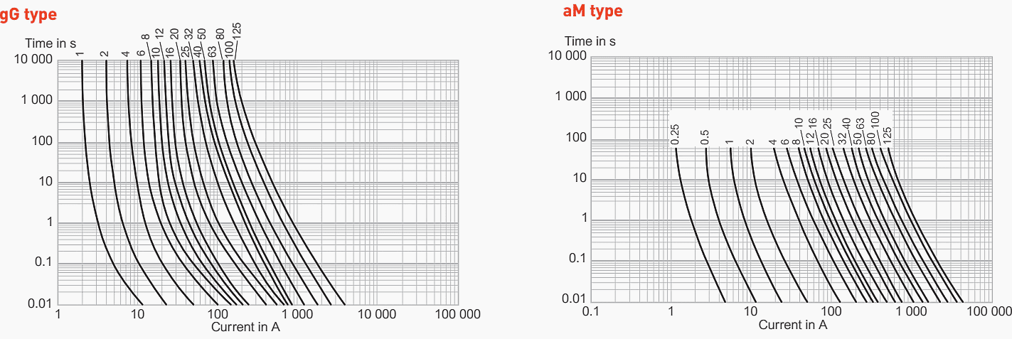
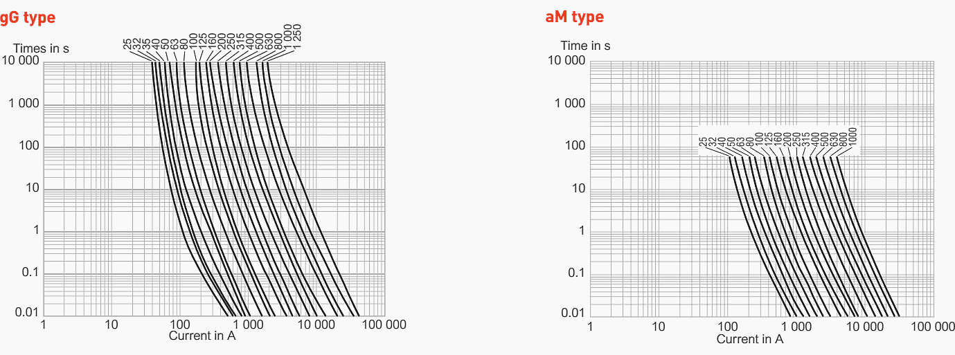
4. Operating zone
The operating zone defined by the standards is used to determine the operating time of the fuse according to the current crossing it. It is important to know the operating characteristics of the fuse in order to calculate the discrimination of the various protective devices installed in series.

For a 100 A, 22 × 58 gG cartridge, an overload of 300 A will melt the cartridge in 40 s.
5. Breaking Capacity
The breaking capacity must be at least equal to the prospective short-circuit current that may occur at the point at which the fuse is installed. The higher the breaking capacity, the more capable the fuse of protecting the installation against high intensity short circuits.
HBC (High Breaking Capacity) fuses limit short circuits that could reach more than 100 000 A rms.
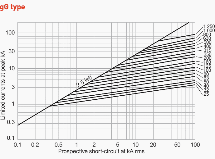
6. Limitation Curve
The limitation of the current can vary according to the conditions of the short circuit (intensity, cos ϕ, short-circuit starting angle ψ). The limitation curves of cartridges represent the maximum limited current values that can be achieved under the most unfavourable conditions.
Example
For a prospective short circuit of 10 000 A rms (or 10 kA rms) in view of the maximum asymmetry of the current, the short circuit could reach a theoretical maximum value of 2.5 × Irms, i.e. 25 kA peak.

The 100 A gG cylindrical fuse cartridge limits the first current wave to 8 000 A peak, i.e. approximately 30% of the prospective maximum value. The destructive electrodynamic effects are therefore reduced by a factor of 10 ( (8 000/25 000)2) of the maximum value.
Importance of the limitation capacity
A short circuit is dangerous, both in terms of its electrodynamic effects and its thermal effects:
The destructive electrodynamic effects depend on the square of the peak current reached during the short circuit, and cause mechanical damage to the insulation of the conductors.
The destructive thermal effects depend on the thermal energy dissipated during the short circuit, and could burn the insulation of the conductors. Fuse cartridges limit both these effects as much as possible.
Planning and installation of the low voltage switchgear – The devil is in the detail!
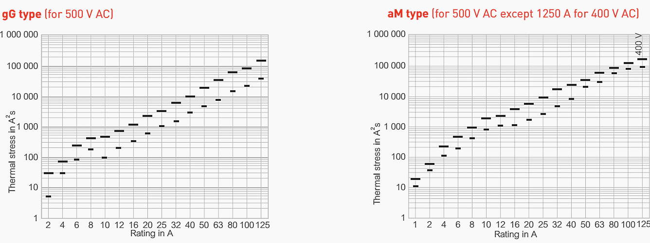
7. Limited Thermal Stress
A short circuit triggers the release of a considerable amount of energy. The fuse cartridge limits this energy to a much lower value, conventionally known as the limited thermal stress, expressed in A2s.
Why must the thermal stress be limited?
If the energy released by the short circuit is not limited, it can quickly lead to total or partial destruction of the installation. Thermal stress is governed by two main parameters:
- Cos ϕ: the lower this is, the greater the energy
- Voltage: the higher the voltage, the greater the energy
Difference between pre-arcing and arcing thermal stresses
A fuse breaks a short circuit in two stages: pre-arcing, then arcing. Let’s say a word about each stage:
The pre-arcing thermal stress corresponds to the minimum energy necessary for the fuse element of the cartridge to start melting. It is important to know this thermal stress in order to determine the selectivity on a short circuit between several protection systems in series.
The arcing thermal stress corresponds to the energy limited between the end of pre-arcing and total breaking.

The sum of the arcing and pre-arcing thermal stresses gives the total thermal stress.

8. Selectivity
A current generally crosses a number of protection devices in series. These devices are calculated and distributed according to the various circuits to be protected. There is selectivity when only the device protecting the faulty circuit operates.
Example
Only the 25 A cartridge has operated on a fault occurring on the line it is protecting. If the 100 A cartridge, or even the 400 A cartridge, had also operated (incorrect selectivity), the whole installation would have gone down.
9. Cylindrical cartridge fuses gG and aM types
Rupture capacity curves
Thermal stress (∫i2dt)
Limitation curves

10. Blade cartridge fuses gG and aM types
Rupture capacity curves
Thermal stress (∫i2dt)

Limitation curves
Source: Breaking and protection devices by Legrand
Related electrical guides & articles


Edvard Csanyi
Hi, I'm an electrical engineer, programmer and founder of EEP - Electrical Engineering Portal. I worked twelve years at Schneider Electric in the position of technical support for low- and medium-voltage projects and the design of busbar trunking systems.I'm highly specialized in the design of LV/MV switchgear and low-voltage, high-power busbar trunking (<6300A) in substations, commercial buildings and industry facilities. I'm also a professional in AutoCAD programming.
Profile: Edvard Csanyi

I have been in Electrical maintenance activities for two decades and i felt my ignorance on type of curves to be verified for Fuses .
Thank you very much for the clear cut explanation of their functioning.
I want to learn
Very interesting insight of how select a cartridge fuses. Good work done
Edvard, THIS IS AN ARTICLE PER EXCELLENCE.
Thank you Olusiji.