
Harmonics and Network Design
Nowadays, if you do not consider harmonics distortion when designing a new network, you missed the whole point of the network design. Yes, really. The sooner you realize that harmonics problems are on the rise, the better. Modern power networks are already pretty dirty because of mass non-linear loads installed without any prior consultation with experts or power analysis.
 Practical design knowledge in harmonics distortion and power factor correction (PFC)
This technical article will shed some light on practical ways of looking at the problems with harmonics distortion. It will also refresh your knowledge in the basics of harmonics and give you some good practical tips in designing, installation and protecting PFC (power factor correction) systems and measures.
The article contains examples of capacitor banks and PFC systems by German manufacturer Frako.
- Harmonics Facts and Questions
- Designing for networks with harmonics
- Installation of Power Factor Correction (PFC)
1. Harmonics Facts and Questions
1.1 What are Harmonics?
Modern low voltage networks increasingly have loads installed that draw non-sinusoidal currents from the power distribution system. These load currents cause voltage drops through the system impedances which distort the original sinusoidal supply voltage. Fourier analysis can be used to separate these superposed waveforms into the basic oscillation (supply frequency) and the individual harmonics.
The frequencies of the harmonics are integral multiples of the basic oscillation and are denoted by the ordinal number ‘n’ or ‘ν’ (Example: Supply frequency = 50 Hz → 5th harmonic = 250 Hz).
Linear loads are ohmic resistances (resistance heaters, light bulbs, etc.), three-phase motors and capacitors, and they are not harmful to the power system.
The most problematic loads that need attention!
Non-linear loads (harmonics generators) are:
- Transformers and chokes
- Electronic power converters
- Rectifiers and converters, especially when controlling variable-speed induction motors
- Induction and electric arc furnaces, welding equipment
- Uninterruptible power supplies (UPS systems)
- Single-phase switched-mode power supply units for modern electronic loads such as televisions, VCRs, computers, monitors, printers, telefax machines, electronic ballasts, compact energy-saving lamps.
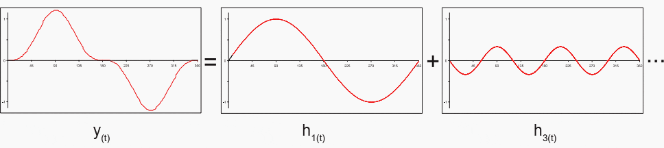
Every periodic signal with a frequency f (regardless of the waveform) consists of the sum of the following:
- The sine component of the frequency f, known as the fundamental component or h1
- The sine components of the integral multiples of the frequency f, known as the harmonics hn
- In some cases DC components can also be present
y(t) = h1(t) + h3(t) …
Figure 1 – Analysing a periodic signal into its component harmonics
Harmonics can be divided into three categories:
1. Even harmonics (2nd, 4th, 6th, etc.)
Even harmonics (2nd, 4th, 6th, etc.) as a rule only occur due to sudden load variations or faults in converters.
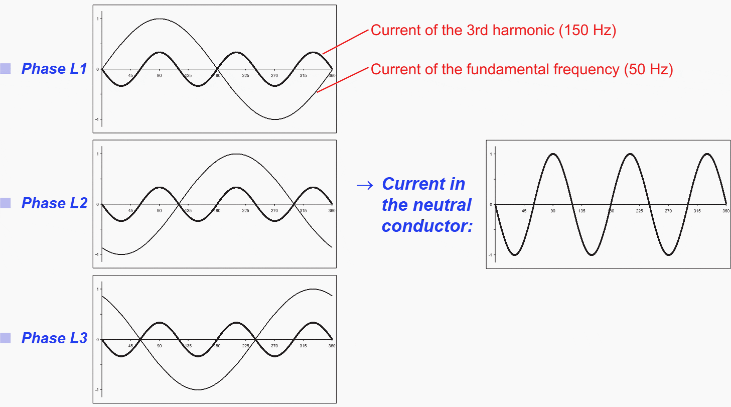
2. Odd harmonics (3rd, 5th, 7th, etc.)
Harmonics divisible by 3 (3rd, 9th, 15th, etc.) occur due to asymmetrical loads and single-phase sources of harmonics. Typical sources are office buildings, hospitals, software companies, banks, etc., factories with 2-phase welding equipment.
The problem they cause: The harmonic currents in the neutral conductor are cumulative.
Figure 2 – Cumulative effect of the 3rd harmonic current in the neutral conductor
3. Harmonics not divisible by 3 (5th, 7th, 11th, 13th, etc.)
Harmonics not divisible by 3 (5th, 7th, 11th, 13th, etc.) occur due to 3-phase sources of harmonics 5th and 7th harmonics: from 6-pulse converters 11th and 13th harmonics: from 12-pulse converters
The problem they cause: The harmonics are transmitted via the transformer! The total harmonic distortion THD is the result of the vector addition of all harmonics present and is, as a rule, expressed as a proportion of the fundamental frequency, thus providing a quick overview of network power quality.
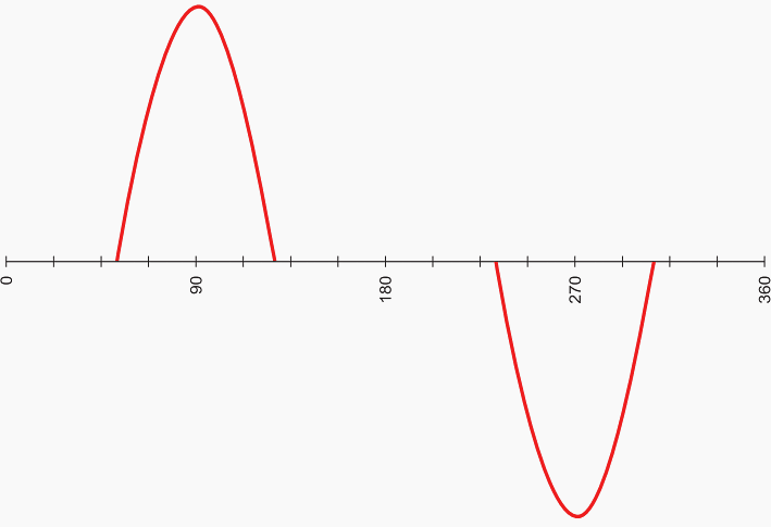
Harmonics are generated not only in industrial installations but also increasingly in private households. As a rule, the devices generating these harmonics only feed in the odd orders, so that it is only the 3rd, 5th, 7th, 9th, 11th, etc. harmonics that are encountered.
Figure 3 – Network current and voltage superposed with the following harmonics: 5% of the 5th harmonic, 4% of the 7th harmonic and 2.5% of the 11th harmonic

Go back to the Contents Table ↑
1.2 How are harmonics produced?
Harmonics are usually produced in a commercial facility’s own low voltage network, especially when variable-speed drives are installed. They are also generated in every household: in every television, computer and in compact energy-saving lamps with electronic ballasts.
The sheer number of these loads in the evenings with the currents in phase gives rise to high levels of harmonics in some medium voltage networks.
1.2.1 Level of harmonics if no PFC system has yet been installed
a) In a facility’s own Low-Voltage system
The level of harmonics if no PFC system has yet been installed in a facility’s own LV system depends on the power of the installed converters and rectifiers. If, for example, a large 6-pulse converter is installed in the network and its power rating is 50% of the transformer nominal rating, this gives rise to about:
- 4% of the 5th harmonic (250 Hz) and
- 3% of the 7th harmonic (350 Hz)
If, for example, several rectifiers with a combined power of some 25% of the transformer nominal rating are installed, this gives rise to some:
- 1 – 1.5% of the 5th harmonic and
- 0.7 – 1% of the 7th harmonic.
These are approximate values to help in the initial assessment of whether a detuned PFC system needs to be installed.
Figure 4 – Current of a power rectifier
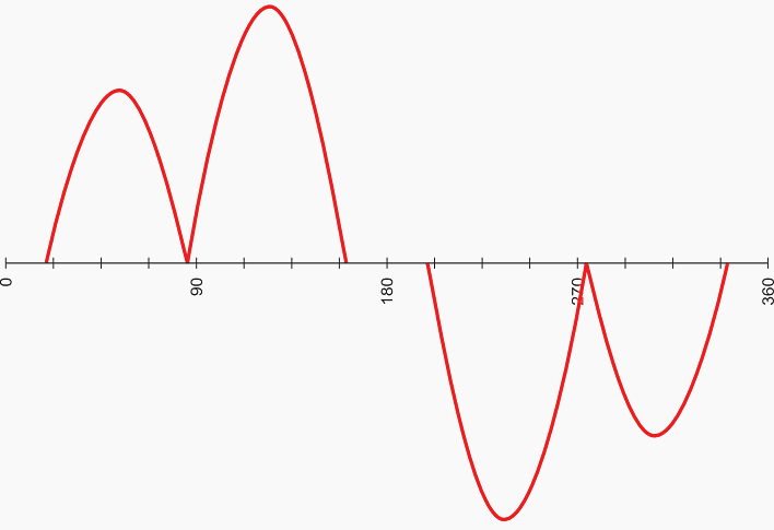
Figure 5 – Line current of a converter for induction motors
b) In the medium voltage supply system
Nowadays, most of these systems are affected predominantly by the devices in private households (mainly television sets) that produce harmonics. This is readily apparent when the daily curve for the 5th harmonic is examined:
Figure 6 – Average and maximum levels of the 5th harmonic as %

The level of harmonics in the medium voltage system of a municipal power supply with industrial loads on weekdays. In densely populated areas in the evenings, frequencies of about 4% 250 Hz and up to 1.5% 350 Hz can be superposed on the medium voltage supply system. The higher harmonics are usually negligible.
Go back to the Contents Table ↑
1.3 What effect does a PFC system have on a network with harmonics?
A PFC system with no detuning (Figure 7) forms an oscillatory circuit with reactive line impedances. The resonant frequency is given by a simple rule of thumb:
fr = 50 Hz × √(Sk/Qc)
where:
- Sk – short-circuit power at the point where the correction system is connected
- Qc – correction system capacitor power rating
The short-circuit power Sk at the point where the PFC system is connected is:
- Determined essentially by the transformer (Sn/uk),
- Reduced by some 10% by the impedance of the medium-voltage system
- Possibly greatly reduced by long lengths of cable between the transformer and the PFC system.
1.3.1 Example
- Transformer 1000 kVA, uk = 6%
- Short-circuit power of the medium voltage system 150 MVA, Sk ≈ 12.6 MVA
- PFC system 400 kvar in 8 stages, not detuned
Table 1 – Capacitor power ratings and resonant frequency
| Capacitor power rating (QC) | Resonant frequency (fr) |
| 100 kvar | 562 Hz |
| 250 kvar | 355 Hz |
| 400 kvar | 281 Hz |
When the capacitor stages of the correction system are switched in, the network resonant frequency (fr) changes considerably and is repeatedly close to the frequency of a network harmonic. If the natural resonance of this oscillatory circuit is near to a network harmonic that is present, it is to be expected that resonance will increase the harmonic voltages.
Under certain conditions, these may be multiplied by an amount approaching the network Q-factor (in industrial systems about 5-10!):
Figure 8 – Amplification factor for harmonic voltages in PFC system without detuning in the low voltage network

Go back to the Contents Table ↑
1.4 When can dangerous network resonances occur?
From Figure 8 above it can be seen that it is possible to assess whether resonance problems can occur with harmonics. Simple rules suffice for this:
1. If the resonant frequency is:
- 10% below/above a network harmonic, the latter will be amplified in a network with a high Q-factor (e.g. in the evenings and at night) by a factor of up to 4.
- 20% above a network harmonic, the latter will be amplified in a network with a high Q-factor by up to 2.5.
- 30% above a network harmonic, the latter will be amplified only slightly, by a factor of up to about 1.7.
2. In a network with no harmonic generator of its own, but with pronounced harmonics present in the medium voltage system, the following can occur:
- at a resonant frequency below 400 Hz – resonance peaks of the 7th harmonic,
- at a resonant frequency below 300 Hz – dangerous resonance peaks of the 5th harmonic (250 Hz).
Go back to the Contents Table ↑
1.5 What effect does the network configuration have on the problem of harmonics?
The network short-circuit power determines the resonant frequency and, where harmonic generators are present in that network, the amplitude of the harmonics in the network voltage.
- If the network short-circuit power at the point where the PFC system is connected is too low, this causes problems.
- If the short-circuit power is changed radically due to altered switching conditions, this causes problems.
Example of large commercial facilities
In many large commercial facilities, continuity of power supply is achieved by connecting the low voltage distribution points via a ring circuit. This network has a high short-circuit power even with large PFC systems and heavy rectifier loads with hardly any harmonics problems arising since the resonant frequency is high and the harmonic currents are dissipated with low voltage drops into the medium voltage system.
If a break is made in the ring circuit, for example for maintenance work, the short-circuit power can decrease considerably under certain conditions, so that the resonant frequency can fall below 300 Hz!
Go back to the Contents Table ↑
1.6 Voltage and current loads on PFC systems without detuning
When resonance occurs, the network r.m.s. voltage only increases slightly, but the r.m.s. value of the capacitor current increases considerably.
In the case of resonance with the fifth harmonic, this can reach a level of, say, 15% in which case:
- The network r.m.s. voltage increases by 1%
- The crest working line voltage increases by 10-15% (depending on phase angle)
- The r.m.s. value of the capacitor current increases by 25%!
In the case of resonance with the 11th harmonic, this can reach a level of, say, 10% in which case:
- The network r.m.s. voltage increases by 0.5%
- The peak value of the mains voltage increases by 6-10%
- The r.m.s. value of the capacitor current increases by 50%!
Go back to the Contents Table ↑
2. Designing for networks with harmonics
What must be done if resonance is possible but rather unlikely? A considerable proportion of installations being designed today fall into this category, e.g.:
- No internal harmonic generators installed in the network, no harmonics in the medium voltage system, but a resonant frequency below 400 Hz.
- If changes are made in the network configuration, for example, during maintenance work, the resonant frequency can fall below 400 Hz. Harmonics are present in the medium voltage distribution system.
- It is planned to build installations with rectifiers at a later date.
The peak values that have occurred are stored, however, and can be retrieved via the EMA 1101 bus interface.
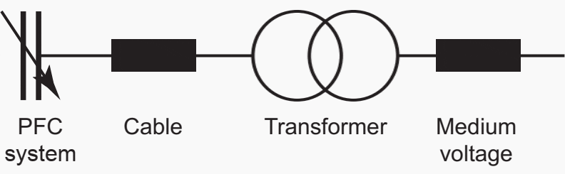
Figure 9 – Direct connection of Mains Monitoring Instrument to low voltage system
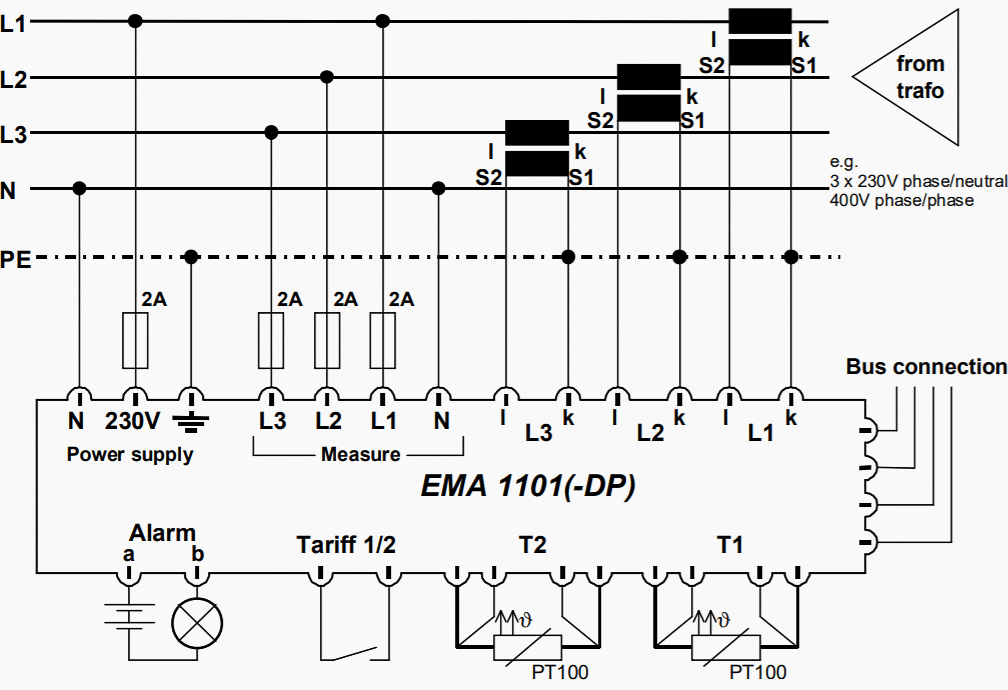
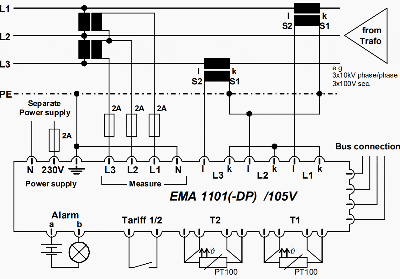
Figure 10 – Connection of Mains Monitoring Instrument to medium-voltage system
For distribution systems that are symmetrically loaded, the Power Factor Control Relay can also be installed. This instrument monitors the system to detect any resonance that may occur. For example, FRAKO’s EMR 1100 power factor control relay determines the harmonic voltages in the measured phase and calculates the r.m.s. current to the capacitors. If a programmed maximum limit is exceeded, the installation is shut down and switched in when the level falls below its critical value.
In cases of this description, PFC systems that can be retrofitted with detuning are often installed.
Figure 11 – Power Factor Control Relay, type ‘EMR 1100’ by FRAKO manufacturer

Go back to the Contents Table ↑
2.1 Planning for PFC systems in networks with harmonics
The best information on the operational characteristics of a planned PFC system is obtained by a combination of two planning activities:
- Measuring the harmonic voltages and currents over several days with no PFC system installed.
- Theoretical calculation of the network resonance characteristics.
In the measured network, the following harmonic levels are to be expected with PFC: Maximum value of measurement without power factor correction multiplied by the resonance factor from the network analysis.
Go back to the Contents Table ↑
2.1.1 Example
An average-size low voltage system with a 1000 kVA transformer. The installation, complete with the PFC system, is connected via two 20 m long cables laid in parallel (equivalent to the impedance of a 10 m cable). Only purely ohmic loads may be taken into account as equipment such as induction motors have no damping effect on harmonics.
During the day, with increased network damping, these factors are lower, but in the evenings and at weekends the amplification factor for the 7th can be higher.
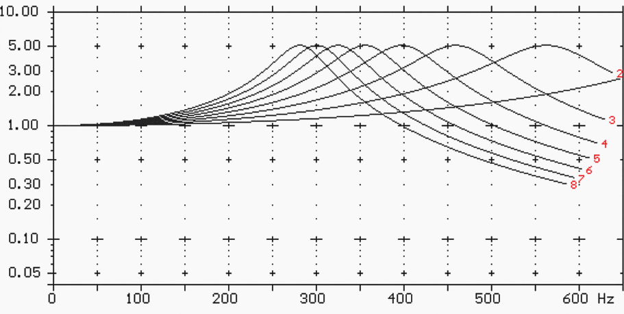
Figure 12 – Amplification of harmonic voltages as a function of the capacitor stages switched in FRAKO – Mains Analysis
Go back to the Contents Table ↑
2.2 Measures to counteract expected resonances
If harmonics with high voltage levels, such as:
- 4% of the 3rd harmonic (150 Hz)
- 5% of the 5th harmonic (250 Hz)
- 4% of the 7th harmonic (350 Hz)
- 3% of the 11th harmonic (550 Hz)
- 2.1% of the 13th harmonic (650 Hz)
due to resonance induced amplification are anticipated when planning a PFC system, serious disruptions can occur in the low voltage distribution systems with:
- Problems with IT systems and CNC machines
- Damage to rectifiers and/or converters
- Uncontrolled tripping of a variable capacitor bank and circuit breakers
- The shutdown of PFC systems without detuning
- Voltage peaks in the distribution system
- Increased eddy current losses in transformers and induction motors
Detuning reduces the resonant frequency to a value below 250 Hz. All harmonics above the resonant frequency of the detuned system are attenuated.
Figure 13 – Damping of harmonic voltages as a function of the detuned capacitor sections
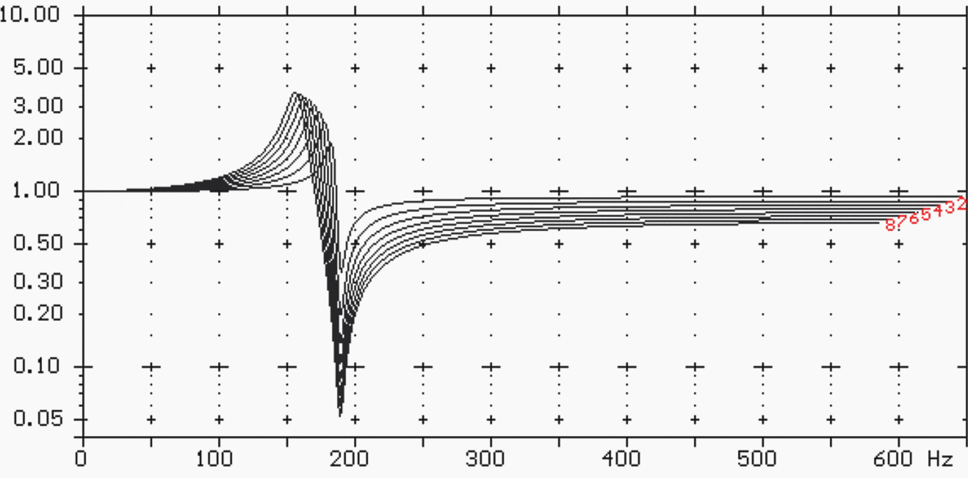
A detuned capacitor consists of a capacitor in series with a filter reactor. Its series resonant frequency is adjusted by the appropriate design of the filter reactor so that it is below the frequency of the 5th harmonic (250 Hz). This combination, therefore, has an inductive characteristic for all frequencies above the series resonant frequency.
The resonance between the capacitors and the reactive network impedances is no longer possible. A detuned system suppresses some of the harmonic currents. To prevent overloads due to the 5th harmonic still present in the network, it is a present-day practice to adjust the resonant frequency of the detuned circuit to 189 Hz or less.
The detuned circuit is characterized either by the capacitor-choke resonant frequency (fr) or by the relative voltage drop (p) at the choke. These two parameters are related by the following:
fr = 50 Hz × √(1/p)
Example:
p = 0.07 (7%)
fr= 189 Hz
Go back to the Contents Table ↑
3. Installation of Power Factor Correction (PDF)
3.1 Current transformer location
A current transformer is necessary to operate PFC systems. This is not included in the scope of supply but can be provided with the system after clarification of user requirements. The primary current in the transformer is determined by the user’s current input, i.e. this unit is designed for the maximum current loading or the installed load connected to the power transformer.
The internal power consumption in the control relay current circuit amounts to some 1.8 VA for a current transformer of rated current 5 A.
Figure 14 – Correctly installed current transformer registers load current and capacitor current


If further instruments need to be powered from the same current transformer, this must be taken into account when specifying its rating. Losses also occur in the current transformer wiring and these must also be taken into account if there are long lengths of cable between the current transformer and the reactive power control relay.
Power losses in copper conductors from the current transformer with a secondary current of 5 A are displayed in Table 2.
Table 2 – Power losses in copper conductors
| Cross-section [mm²] | Losses per metre of the two-wire line [VA] |
| 2.4 | 0.36 |
| 4.0 | 0.22 |
| 6.0 | 0.15 |
| 10.0 | 0.09 |
NOTE! The current transformer must be installed in one of the three phases so that the entire current to the consumers requiring PFC and the capacitor current flow through it (as shown in Figures 14 and 15). Terminal P1 (K) is connected to the supply side, terminal P2 (L) to the consumer side.
CAUTION! When the primary circuit is broken, voltage surges occur which could destroy the current transformer. The terminals S1 (k) and S2 (l) must therefore be short-circuited before the transformer circuit is broken.
Go back to the Contents Table ↑
3.2 Overcurrent protection and cables
When installation work is carried out, the regulations IEC 60364-6 and IEC 60831 the conditions of supply of the utility company concerned must be complied with. IEC 60831 states that capacitor units must be suitable for continuous r.m.s. current of 1.3 times the current that is drawn at the sinusoidal rated voltage and nominal frequency.
If the capacitance tolerance of 1.1 × CN is also taken into account, the maximum allowable current can reach values of up to 1.38 × IN. This overload capability together with the high inrush current to the capacitors must be taken into account when designing protective devices and cable cross-sections.
Suggested reading – The mystery of nuisance tripping incidents in transformer protection
The mystery of nuisance tripping incidents in transformer protection that worry engineers
Go back to the Contents Table ↑
3.3 Ingress protection
The standard EN 60529 specifies the degree of protection for electrical enclosures by means of two letters and a two-digit number. IP stands for ingress protection, while the first and second numbers specify the protection against solid objects and liquids respectively.
Suggested reading – Enclosure protection against ingress of solid objects and liquids
Enclosure protection against ingress of solid objects and liquids
Go back to the Contents Table ↑
Sources:
- Manual of Power Factor Correction by Peter Riese
- Mains Monitoring Instrument EMA 1101 / EMA 1101-DP – Operating Instructions by FRAKO
- Reactive Power Control Relay EMR 1100 /-S – Operating Instructions by FRAKO
Related electrical guides & articles


Edvard Csanyi
Hi, I'm an electrical engineer, programmer and founder of EEP - Electrical Engineering Portal. I worked twelve years at Schneider Electric in the position of technical support for low- and medium-voltage projects and the design of busbar trunking systems.I'm highly specialized in the design of LV/MV switchgear and low-voltage, high-power busbar trunking (<6300A) in substations, commercial buildings and industry facilities. I'm also a professional in AutoCAD programming.
Profile: Edvard Csanyi

Good
What if there’s no PE program ( there’s no ground rods on transformer making the X0) when there is improper cabling the place I work the oil mill they use THNN cable on VFDs instead XPL cabling, harmonics are a parent instead of 480 voltage they have 525 voltage.
Okay, I have installed VFDs and knowing you are supposed to go with manufacturers specifications in cabling and install in clean atmosphere areas.
Question is can you send me more information about VFDs please.
How do you address harmonics in FPSOs, drilling rigs, semi-subs, and offshore units in general?