High resistance grounding equipment or permanently installed electrical distribution systems used in mines should be selected and applied as recommended for process industries.
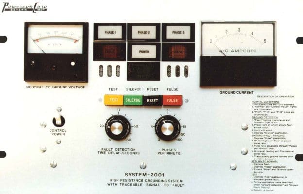
When mobile equipment is connected to the distribution system the grounding equipment and the ground fault protection should be designed to comply with CSAStd. M421-00 Use of Electricity in Mines, which requires that:
Mobile equipment operating at more than 300 volts shall have ground fault protection and ground conductor monitoring. The neutral be grounded through a neutral grounding device in such a manner as to limit the possible rise of ground fault potential to a maximum of 100 volts.
Although the code requires instantaneous fault clearing in coal mines (Paragraph 6.11.2), time delayed tripping is generally acceptable in other mining operations. Local mining codes should be checked for time delay requirements.
The impedance of the ground wire shall not exceed the values to limit the voltage drop external to the Grounding Resistor to maximum 100 volts.
Maximum ground impedance for mining
| Resistor rating (amps) | Max. ground wire impedance (ohms) | Product I X R (V) |
| 5 | 20 | 100 |
| 10 | 10 | 100 |
| 15 | 6.5 | 100 |
| 25 | 4 | 100 |
| 50 | 2 | 100 |
Current and voltage sensing ground fault protection
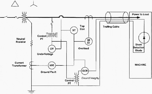
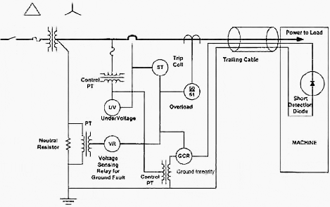
The permitted ground wire impedance is the sum of the impedance of the grounding conductor of all trailing cables. The resistance value of the grounding device is normally designed to operate a selected ground relay at the highest sensitivity level to provide maximum protection.
It is recommended that the pick-up of the Ground Fault Relay shall be 5 amps or less when used with a current relay, or 80% when a volt-age relay is used. Typical protection systems are shown in Figure 1a (current relay) and Figure 1b (voltage relay).
NOTE – The one advantage of using a potential transformer in place of the current transformer for the ground fault protection is that the potential transformer monitors the continuity of the neutral grounding resistor, such that an open circuit in the resis-tor would cause early operation of the voltage relay (VR).
Redundancy is often obtained by the use of both current sensing and voltage sensing.
For medium voltage applications and when increased insulation levels are required on low voltage systems, the types SHD and SHD-GC cables should be used. Both types are available with cross-linked polyethylene or ethylene-propylene (EPR) insulation with natural rubber, polyethylene, polychloroprene or polyurethane jacket for 5 KV, 8 KV and 15 KV insulation level. The type SHD cables are made with three unin-sulated ground wires, one in each interstice.
The type SHD-GC cables are made with one insulated AWG. No. 8 ground check and two uninsulated ground wires, one in each interstice.
When individual power conductor shielding is not required, type G (SGO) portable cables can be used for low voltage applications. The type G cables are made with 3 uninsulated ground wires, one in each interstice.
Cables operating on circuits over 750 volts or, in coal mines, over 125 volts must have a grounded shielding consisting of tinned copper wire mesh, or the equivalent; and this shielding shall be, throughout the length of the cable, in contact with the interstitial grounding conductor. (Paragraph 4.1.2.10 of CSA Std. C22.5-1977).
Resource: Ground Fault Protection on Ungrounded and High Resistance Grounded Systems – iGard





Thank you all materies. This is very important for my job. But i want ask, how to method commissioning procedure generator power plant