
Estimated Study Time: 12 minutes
High Voltage Station – 3 Main Processes
The development of a high-voltage (HV) substation is a massive multidisciplinary undertaking. Recent trends in utilities have heavily favored sourcing the design and construction of HV stations through EPC (Engineering, Procurement, and Construction) or turnkey contracts. Regardless of the procurement method, bringing a substation from an empty plot of land to a fully energized node on the grid follows three distinct, highly regulated phases.
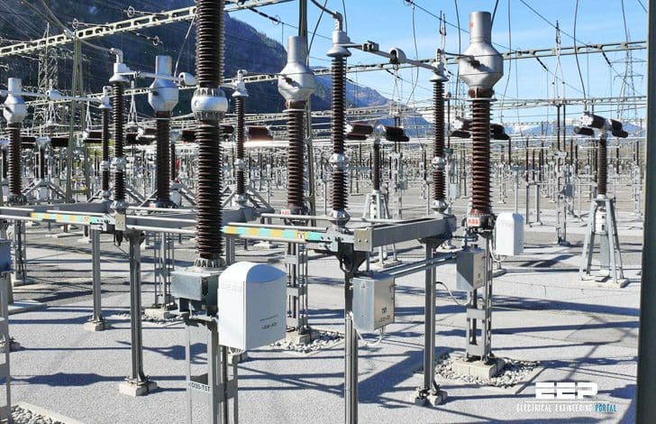 High voltage station – Design, construction and commissioning process (on photo: Construction of 400 kV SF6 switching station; credit: gruner.ch)
Here is a technical overview of the core lifecycle of an HV station.
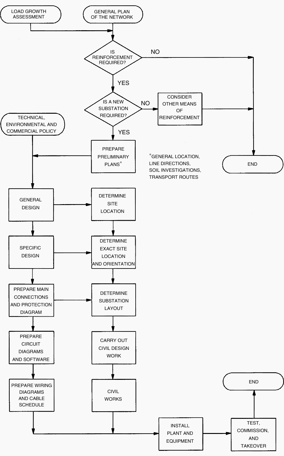
Having selected the right site location for high voltage station, the design construction and commissioning process would broadly follow the steps shown in Figure 1. Recent trends in utilities have been toward sourcing design and construction of HV stations through competitive bidding process to ensure capital efficiency and labor productivity.
Now, let’s start discussing the three main phases:
- Phase 1: Design and Engineering
- Phase 2: Construction and Installation
- Phase 3: Testing and Commissioning
1. Phase 1: Design and Engineering
The engineering phase sets the foundation for the entire project. Once the optimal site is selected—balancing right-of-way access, environmental impact, and grid topology—electrical and civil engineers collaborate to produce the blueprints.
Primary System Design
The starting point is defining the Single Line Diagram (SLD) and selecting the busbar configuration (e.g., double bus, breaker-and-a-half).
Engineers must size and specify the primary high-voltage equipment, including power transformers, circuit breakers, disconnectors, and instrument transformers, while deciding between Air-Insulated Switchgear (AIS) and Gas-Insulated Switchgear (GIS).
Secondary System and Automation Design
A critical shift in modern station design is the implementation of digital substation architectures. Engineers must carefully map out the Station and Process Buses in strict accordance with the IEC 61850 standard (utilizing IEC 61850-8-1 for station level communication and IEC 61850-9-2 for sampled values on the process bus).
This involves selecting Intelligent Electronic Devices (IEDs) and standardizing on highly reliable protection relays, such as the MICOM or SIPROTEC families, to execute complex protection algorithms.
Cybersecurity and IT/OT Convergence
As operational technology (OT) converges with IT, the network architecture becomes a critical design parameter. Engineers must design redundant, fail-safe networks using protocols like PRP (Parallel Redundancy Protocol) or HSR (High-availability Seamless Redundancy).
Identifying and mitigating cyber-physical attack vectors through strict network segmentation and firewall configurations is now a mandatory step before any hardware is ordered.
Now the final detailed designs can be developed along with all the drawings necessary for construction. The electrical equipment and all the other materials can now be ordered and detailed schedules for all disciplines negotiated. Final manpower forecasts must be developed and coordinated with other business units.
Once the designs are completed and the drawings published, the remaining permits can be obtained.
The following can be used as a guide for various design elements:
Basic Layout
- Stage development diagram
- Bus configuration to meet single line requirements
- Location of major equipment and steel structures based on single line diagram
- General concept of HV station
- Electrical and safety clearances
- Ultimate stage
Design
- Site Preparation – Drainage and erosion, earth work, roads and access, and fencing
- Foundations – Soils, concrete design, and pile design
- Structures – Materials, finishes, and corrosion control
- Buildings
- Control, metering, relaying, and annunciation buildings — types such as masonry, prefabricated, etc.
- Metalclad switchgear buildings
- GIS buildings
- Mechanical Systems
- HVAC
- Sound enclosure ventilation
- Metalclad switchgear or GIS buildings ventilation
- Fire detection and protection
- Oil sensing and spill prevention
- Buswork
- Rigid buses
- Strain conductors – swing, bundle collapse
- Ampacity
- Connections
- Phase spacing
- Short circuit forces
- Insulation – Basic impulse level and switching impulse level
- HV Station Insulators
- Porcelain post type insulators
- Resistance graded insulators
- Polymeric post insulators
- Subtation insulator hardware
- Selection of subtation insulator – TR – ANSI and CSA standard
- Pollution of insulators – pollution levels and selection of leakage distance
- Suspension Insulators
- Characteristics
- Porcelain suspension insulators
- Polymeric suspension insulators
- Suspension insulators hardware
- Selection of suspension insulators
- Pollution of insulators – pollution levels and selection of leakage distance
- Clearances
- Electrical clearances
- Safety clearances
- Overvoltages
- Atmospheric and switching overvoltages
- Overvoltage protection – pipe and rod gaps, surge arresters
- Atmospheric overvoltage protection – lightning protection (skywires, lightning rods)
- Grounding
- Function of grounding system
- Step, touch, mesh and transferred voltages
- Allowable limits of body current
- Allowable limits of step and touch voltages
- Soil resistivity
- General design guidelines
- Neutral Systems
- Background of power system grounding
- Three and four wire systems
- HV and LV neutral systems
- Design of neutral systems
- HV Station Security
- Physical security
- Electronic security
Go back to HV station processes ↑
2. Phase 2: Construction and Installation
With the design approved, civil and electrical teams mobilize to the site to translate the engineering models into physical infrastructure.
Civil Works and Earthing
Construction begins with site grading, trenching, and pouring the foundations. Concurrently, the critical earth grid (grounding mat) is laid and bonded. Achieving a low earth electrode resistance is paramount to ensure touch and step potentials remain within safe physiological limits during a fault.
Primary Equipment Erection
This involves the heavy lifting and precise mechanical alignment of the primary plant. Transformers are rolled onto their plinths, and circuit breakers and switchgear are erected. If the design utilizes GIS, strict clean-room protocols must be enforced during the bolting and coupling of the SF6 gas compartments to prevent internal contamination.
Secondary Installation and Cabling
In a conventional station, kilometers of copper control cables are pulled through trenches. However, in modern digital implementations, the physical footprint of trenches is drastically reduced. Copper is largely replaced by fiber optic cables connecting the switchyard’s field-mounted merging units directly to the protection relays in the control building.
With permits in hand and drawings published, the construction of the substation can begin. Site logistics and housekeeping can have a significant impact on the acceptance of the facility.
All the civil, electrical, and electronic systems are installed at this time. Proper attention should also be paid to site security during the construction phase not only to safeguard the material and equipment, but also to protect the public.
Go back to HV station processes ↑
3. Phase 3: Testing and Commissioning
Before an HV station can be connected to the grid, it must undergo rigorous validation to ensure every component operates safely under both normal loads and extreme fault conditions.
Factory Acceptance Testing (FAT)
Conducted at the manufacturer’s facility before shipping. FAT verifies that individual components—from the massive power transformers to the control panels and IEDs—perform exactly to the specified engineering parameters.
Site Acceptance Testing (SAT) and Cold Commissioning
Once installed, equipment is tested without high-voltage grid power. This includes insulation resistance testing (Megger), contact resistance measurements on breakers, and primary injection tests on current transformers.
For the secondary systems, engineers perform secondary injection on the relays to verify the protection logic. In digital substations, this is the crucial stage where SCL (Substation Configuration Language) and XML files are heavily scrutinized to resolve any interoperability failures between different manufacturers’ devices on the IEC 61850 network.
Hot Commissioning and Energization
The final and most hazardous phase. The station is carefully connected to the live grid. Phasing checks are confirmed, voltage is applied, and the load is gradually introduced. All SCADA systems, interlocking logic, and operational parameters are monitored in real-time to ensure the station is stable and ready to be officially handed over to the grid operator.
Elements of inspection, testing and acceptance plan include:
- Factory acceptance tests (FAT)
- Product verification plan (PVP)
- Site delivery acceptance test (SDAT)
- Site acceptance tests (SAT)
Final tests of the completed substation in a partially energized environment to determine acceptability and conformance to customer requirements under conditions as close as possible to normal operation conditions will finalize the in-service tests and turn-over to operations.
Public relations personnel can make the residents and community leaders aware that the project is complete and the station can be made functional and turned over to the operating staff.
Related electrical guides & articles


Edvard Csanyi
Hi, I'm an electrical engineer, programmer and founder of EEP - Electrical Engineering Portal. I worked twelve years at Schneider Electric in the position of technical support for low- and medium-voltage projects and the design of busbar trunking systems.I'm highly specialized in the design of LV/MV switchgear and low-voltage, high-power busbar trunking (<6300A) in substations, commercial buildings and industry facilities. I'm also a professional in AutoCAD programming.
Profile: Edvard Csanyi

Is there much work available in this space for subcontractors?
this is a great site ..
merci
Hi,
I would say there is one major item missing, that is the specification and purchase of main circuit apparatus and auxiliary power systems.