
Estimated Study Time: 47 minutes
Reactive power
We always tend to reduce reactive power to improve system efficiency. This is acceptable at some level. If the system is purely resistive or capacitance, it may cause problems in the Electrical system. AC systems supply or consume two kinds of power: real power and reactive power. Real power accomplishes useful work, while reactive power supports the voltage that must be controlled for system reliability.
Reactive power profoundly affects the security of power systems because it affects voltages throughout the system. Find important discussion regarding the importance of Reactive Power and how it is useful to maintain healthy system voltage.
Table of Contents:
- Need of reactive power
- Importance of present of reactive power
- Purpose of reactive power
- What is reactive power?
- Why do we need reactive power?
- Reactive power is a byproduct of AC systems
- How are voltages controlled?
- Voltage must be maintained within acc. levels
- Voltage and reactive power
- Reactive power and power factor
- Reactive power limitations
- Reactive power caused absence of el. supply
- Problems of reactive power
- Profound effects of reactive power:
- Voltage and reactive power planning
1. Need of Reactive Power
Voltage control in an electrical power system is vital for the proper operation of electrical power equipment. It prevents damage, such as overheating of generators and motors, and reduces transmission losses. The system’s ability to withstand and prevent voltage collapse is also maintained.
In simple terms, the control of voltage involves managing reactive power. Decreasing reactive power causes voltage to drop, while increasing it causes voltage to rise. A voltage collapse occurs when the system attempts to serve a load that exceeds the voltage’s capacity.
When reactive power supplies lower voltage, as voltage drops, current must increase to maintain the power supplied, causing the system to consume more reactive power, and the voltage drops further. If the current increases too much, transmission lines go off line, overloading other lines and potentially causing cascading failures.
This potential for cascading failures underscores the need for proactive measures to prevent such occurrences.
The result of these progressive and uncontrollable declines in voltage is that the system is unable to meet the demand for reactive power. As engineers and technicians, it is our responsibility to ensure that the system is always capable of providing the required reactive power, thereby maintaining the stability of the electrical system.
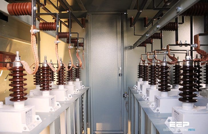
Figure 1 – Installation of new reactive power compensation on power grid
2. Importance of Present of Reactive Power
Voltage control and reactive-power management are two aspects of a single activity that supports reliability and facilitates commercial transactions across transmission networks. On an alternating-current (AC) power system, voltage is controlled by managing the production and consumption of reactive power. There are three reasons why managing reactive power and controlling voltage is necessary.
First, customer and power system equipment are designed to operate within a range of voltages, usually within ±5% of the nominal voltage.
Second, reactive power consumes transmission and generation resources. Reactive power flows must be minimized to maximize the amount of real power that can be transferred across a congested transmission interface. Similarly, reactive power production can limit a generator’s real power capability.
Third, moving reactive power on the transmission system incurs real power losses. Both capacity and energy must be supplied to replace these losses. Two additional factors complicate voltage control.
The transmission system is a nonlinear consumer of reactive power, depending on system loading. At very light loading, the system generates reactive power that must be absorbed, while at heavy loading, the system consumes a large amount of reactive power that must be replaced. The system’s reactive power requirements depend on the generation and transmission configuration.
Useful Study (PDF) – Effects of imbalances and non-linear loads in electricity distribution system
Effects of imbalances and non-linear loads in electricity distribution system
Consequently, system reactive requirements vary as load levels and load and generation patterns change. The bulk-power system is composed of many pieces of equipment, any one of which can fail at any time. Therefore, the system is designed to withstand the loss of any single piece of equipment and to continue operating without impacting any customers. That is, the system is designed to withstand a single contingency.
These two factors result in a dynamic reactive power requirement. The loss of a generator or a major transmission line can compound by reducing the reactive supply and reconfiguring flows such that the system consumes additional reactive power.
Loads can also be real and reactive. The reactive portion of the load could be served by the transmission system. Reactive loads incur more voltage drops and reactive losses in the transmission system than similar-size (MVA) real loads.
Vertically integrated utilities often include charges for providing reactive power to loads in their rates. With restructuring, the trend is to restrict loads to operation at near zero reactive power demand (a 1.0 power factor). The system operator proposal limits loads to power factors between 0.97 lagging (absorbing reactive power) and 0.99 leading.
Maintaining the power system’s reliability is paramount. It is crucial to avoid problems of market power, where a company could use its transmission lines to limit competition for generation and increase its prices. This underscores the need for a robust and reliable power system.
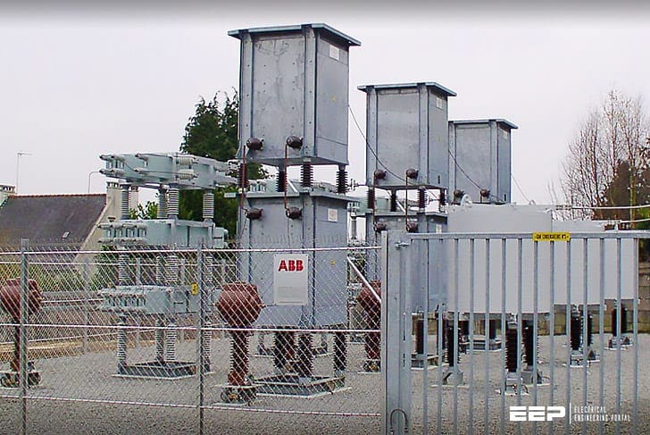
Figure 2 – Control of reactive power in transmission and distribution systems
3. Purpose of Reactive Power
The role of synchronous generators, SVCs, and various types of other DER (Distributed energy resource) equipment in maintaining voltages throughout the transmission system is crucial. The injection of reactive power into the system is a key process that raises voltages, while the absorption of reactive power is equally important as it lowers them.
Voltage-support requirements are a function of the locations and magnitudes of generator outputs, customer loads, and the configuration of the DER transmission system.
System operation has three objectives when managing reactive power and voltages.
First, it must maintain adequate voltages for current and contingency conditions throughout the transmission and distribution system. Second, it seeks to minimize the congestion of real-power flows. Third, it aims to minimize real-power losses.
However, the mechanisms that system operators use to acquire and deploy reactive power resources are changing. These mechanisms must be fair to all parties, effective, and demonstrably fair.
How it works – Do you know what reactive power compensation is? If not, keep reading, it’s important.
Do you know what reactive power compensation is? If not, keep reading, it’s important.
4. What is Reactive Power?
While active power is the energy supplied to run a motor, heat a home, or illuminate an electric light bulb, reactive power provides the important function of regulating voltage. If voltage on the system is not high enough, active power cannot be supplied.
Reactive power is used to provide the voltage levels necessary for active power to do useful work. Reactive power is essential to move active power through the transmission and distribution system to the customer.
Figure 3 – Power triangle representing relations of apparent, reactive and real power

5. Why Do We Need Reactive Power?
Reactive power (VARS) is required to maintain the voltage to deliver active power (watts) through transmission lines. Motor and other loads require reactive power to convert the flow of electrons into useful work.
When there is not enough reactive power, the voltage sags, and the power demanded by loads cannot be pushed through the lines.
Watch Video – Where does the Reactive Power go?
6. Reactive Power is a Byproduct of Alternating Current (AC) Systems
- Transformers, transmission lines, and motors require reactive power.
- Transformers and transmission lines introduce inductance as well as resistance:
- Both oppose the flow of current,
- Must raise the voltage higher to push the power through the inductance of the lines,
- Unless capacitance is introduced to offset inductance.
- The farther the transmission of power, the higher the voltage needs to be raised.
- Electric motors need reactive power to produce magnetic fields for their operation.
7. How Are Voltages Controlled?
Voltages are controlled by providing sufficient reactive power control margin to “modulate” and supply needs through:
- Shunt capacitor and reactor compensations,
- Dynamic compensation, and
- Proper voltage schedule of generation.
Voltages are also controlled by predicting and correcting reactive power demand from loads.
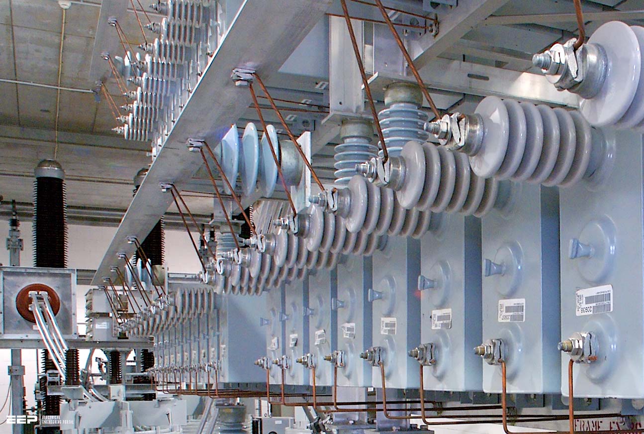
Figure 4 – The installtion of shunt capacitor banks used for improving power transfer
8. Voltage must be maintained within acceptable levels
Under normal system conditions, both peak or off peak load conditions, the voltages need to be maintained between 95% and 105% of the nominal.
Low voltage conditions could result in equipment malfunctions:
- Motor will stall, overheat or damage
- Reactive power output of capacitors will be reduced exponentially
- Generating units may trip.
High voltage conditions may:
- Damage major equipment – insulation failure
- Automatically trip major transmission equipment
Read more – Specific capacitor installations & reactive compensation of asynchronous motors & transformers
Specific capacitor installations & reactive compensation of asynchronous motors / transformers
9. Voltage and Reactive Power
Voltage and reactive power must be properly managed and controlled to:
- Provide adequate service quality
- Maintain proper stability of the power system.
10. Reactive Power and Power Factor
Reactive power is present when the voltage and current are not in phase:
- One waveform leads the other
- Phase angle not equal to 0°
- Power factor less than unity
Reactive Power is measured in volt-ampere reactive (VAR) and it’s produced when the current waveform leads voltage waveform (Leading power factor). Vice versa, it’s consumed when the current waveform lags voltage (lagging power factor).
Figure 5 – Examples of some of the sources of leading and lagging reactive power at the load
11. Reactive Power Limitations
Some of the reactive power limitations are:
- Reactive power does not travel very far.
- Usually necessary to produce it close to the location where it is needed.
- A supplier/source close to the location of the need is in a much better position to provide reactive power versus one that is located far from the location of the need.
- Reactive power supplies are closely tied to the ability to deliver real or active power.
12. Reactive power caused absence of electrical supply in countr
The blackout
The quality of the electrical energy supply can be evaluated based on several parameters. However, the most important will always be the presence of electrical energy and the number and duration of interrupts. If there is no voltage in the socket, nobody will care about harmonics, sags, or surges.
A long-term, wide-spread interrupt—a blackout—leads usually to catastrophic losses. It is difficult to imagine that there is no electrical supply throughout the country. In reality, such things have already happened a number of times. One reason leading to a blackout is reactive power that went out of control.
Figure 6 – Power Triangle

When electrical energy consumption is high, the demand on inductive reactive power increases usually at the same proportion. In this moment, the transmission lines (that are well loaded) introduce an extra inductive reactive power.
Local sources of capacitive reactive power become insufficient. More reactive power must be delivered from generators in power plants.
In continental Europe, most power plants are based on heat and steam turbines. If a generation unit in such a plant is stopped and cooled down, it requires time and electrical energy to start operating again. If the other power plants are also off, the blackout is permanent.
Insufficient reactive power, leading to voltage collapse, has been a causal factor in major blackouts worldwide. Voltage collapse occurred in the United States in the blackouts of July 2, 1996, and August 10, 1996, on the West Coast.
While August 14, 2003, blackout in the United States and Canada was not due to a voltage collapse as that term has traditionally used by power system engineers, the task force final report said that “Insufficient reactive power was an issue in the blackout” and the report also “overestimation of dynamics reactive output of system generation ” as common factor among major outages in the United States.
Demand for reactive power was unusually high because of a large volume of long-distance transmissions streaming through Ohio to areas, including Canada, than needed to import power to meet local demand. But the supply of reactive power was low because some plants were out of service and, possibly, because other plants were not producing enough.
Related Study – Energy Demand Factor, Diversity Factor, Utilization Factor, and Load Factor
Energy Demand Factor, Diversity Factor, Utilization Factor, and Load Factor
13. Problems of reactive power
Though reactive power is needed to run many electrical devices, it can cause harmful effects on your appliances and other motorized loads, and your electrical infrastructure. Since the current flowing through your electrical system is higher than necessary to do the required work, excess power dissipates in the form of heat as the reactive current flows through resistive components like wires, switches and transformers.
Keep in mind that whenever energy is expended, you pay. It makes no difference whether the energy is expended in the form of heat or useful work.
We can determine how much reactive power your electrical devices use by measuring their power factor, the ratio between real and true power. A power factor of 1 (i.e. 100%) ideally means that all electrical power is applied to real work. Homes typically have overall power factors in the range of 70% to 85%, depending upon which appliances are running. Newer homes with the latest in energy-efficient appliances can have an overall power factor in the nineties.
The typical residential power meter only reads real power, i.e. what you would have with a power factor of 100%. While most electric companies do not charge residences directly for reactive power, it’s a common misconception to say that reactive power correction has no economic benefit. To begin with, electric companies correct for power factor around industrial complexes, or they will request the offending customer to do so at his expense or charge more for reactive power.
As stated earlier, electric companies correct for power factor around industrial complexes, or they will request the offending customer to do so or charge for reactive power. They’re not worried about residential service because the impact on their distribution grid is not as severe as in heavily industrialized areas.
However, power factor correction indeed assists the electric company by reducing electricity demand, thereby allowing them to satisfy service needs elsewhere. But who cares? Power factor correction lowers your electric bill by reducing the number of kilowatts expended, and without it your electric bill will be higher, guaranteed.
Detailed expanation of what is Power Factor (PF):
Why should plant engineers be worried about the power factor? What’s the catch?
We’ve encountered this with other electric companies and successfully got each of them to issue a retraction. Electric companies vary greatly, and many show no interest in deviating from their standard marketing strategy by acknowledging proven energy-saving products. Remember that promoting REAL energy savings to all their customers would devastate their bottom line.
Power factor correction will not raise your electric bill or harm your electrical devices. The technology has been successfully applied throughout the industry for years. Power factor correction will enhance the electrical efficiency and longevity of inductive loads when sized properly.
Power factor correction can have adverse side effects (e.g., harmonics) on sensitive industrialized equipment if not handled by knowledgeable, experienced professionals. In residential dwellings, power factor correction is limited to the capacity of the electrical panel (200 amp max) and does not overcompensate household inductive loads.
By increasing the efficiency of electrical systems, energy demand and its environmental impact is lessened.
Figure 7 – An example of a T&D network with reactive power (VAr) compensation
Profound effects of Reactive Power in Various elements of Power System:
Generation
An electric-power generator’s primary function is to convert fuel (or other energy resource) into electric power. Almost all generators also control their terminal voltage and reactive-power output considerably.
Payment for using this resource is the specific focus of voltage control from generation service. The ability of generator to provide reactive support depends on its real-power production. Like most electric equipment, generators are limited by their current-carrying capability. Near rated voltage, this capability becomes an MVA limit for the armature of the generator rather than a MW limitation.
Absorbing large amounts of reactive power reduces the synchronizing torque, which can also limit generator capability to reduce the chance of losing synchronism with the system.
VIdeo Lesson – Synchronization of Machine with Grid
The generator prime mover (e.g., the steam turbine) is usually designed with less capacity than the electric generator, resulting in the prime-mover limit. The designers recognize that the generator will most of the time produce reactive power and support system voltage. Providing a prime mover capable of delivering all the mechanical power the generator can convert to electricity when it is neither producing nor absorbing reactive power would result in underutilization of the prime mover.
To produce or absorb additional VARs beyond these limits would require reducing the unit’s real-power output. Adjusting the DC current in the generator’s rotating field provides control over the reactive output and the terminal voltage of the generator.Control can be automatic, continuous, or fast.
The inherent characteristics of the generator help maintain system voltage. At any given field setting, the generator has a specific terminal voltage it is attempting to hold. If the system voltage declines, the generator injects reactive power into the power system, tending to raise the voltage. If the system voltage rises, the reactive output of the generator will drop, and ultimately reactive power will flow into the generator, tending to lower system voltage.
The voltage regulator will accentuate this behavior by driving the field current in the appropriate direction to obtain the desired system voltage.
Related Reading – Synchronization and Reactive Power Control in Power System
Synchronous condesers
Every synchronous machine (motor or generator) with a controllable field has the reactive-power capabilities discussed above. Synchronous motors are occasionally used to provide dynamic voltage support to the power system as they provide mechanical power to their load. Some combustion turbines and hydro units are designed to allow the generator to operate without its mechanical power source simply to provide the reactive-power capability to the power system when the real-power generation is unavailable or not needed.
Synchronous machines that are designed exclusively to provide reactive support are called synchronous condensers.
They also consume real power equal to about 3% of the machine’s reactive-power rating.
Video Lesson – Synchronous Condensers Part #1
In this lesson we’ll introduce the synchronous condenser. We’ll learn that a synchronous motor uncoupled from a mechanical load can act as a dynamic power factor correction device. We’ll learn that underexcitation of the rotor causes the synchronous condenser to consume positive reactive power as would an inductor and overexcitation of the rotor causes the synchronous condenser to supply negative reactive power as would a capacitor. By managing field current a synchronous condenser can power factor correct a larger 3 phase AC system.
Video Lesson – Synchronous Condensers Part #2
Capacitors and inductors
Capacitors and inductors (which are sometimes called reactors) are passive devices that generate or absorb reactive power. They accomplish this without significant real-power losses or operating expense. The output of capacitors and inductors is proportional to the square of the voltage.
Thus, a capacitor bank (or inductor) rated at 100 MVAR will produce (or absorb) only 90 MVAR when the voltage dips to 0.95 pu but it will produce (or absorb) 110 MVAR when the voltage rises to 1.05 pu. This relationship is helpful when inductors are employed to hold voltages down.
Inductors are discrete devices designed to absorb a specific amount of reactive power at a specific voltage. They can be switched on or off but offer no variable control.
Capacitor banks are composed of individual capacitor cans, typically 200 kVAR or less each. The cans are connected in series and parallel to obtain the desired capacitor-bank voltage and capacity rating. Like inductors, capacitor banks are discrete devices but they are often configured with several steps to provide a limited amount of variable control which makes it a disadvantage compared to synchronous motor.
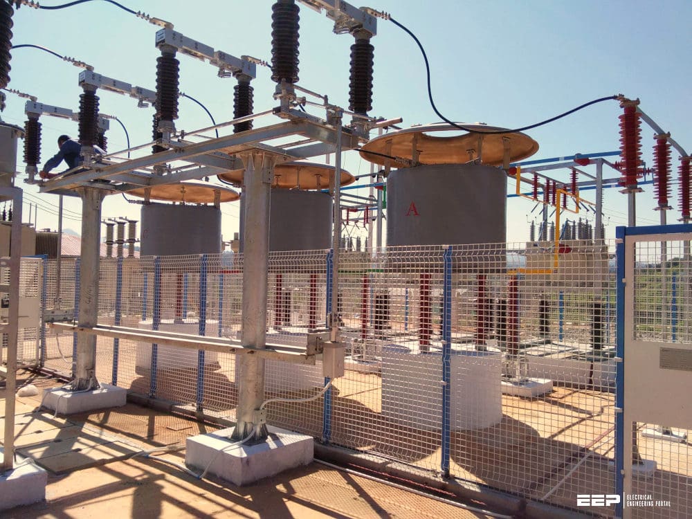
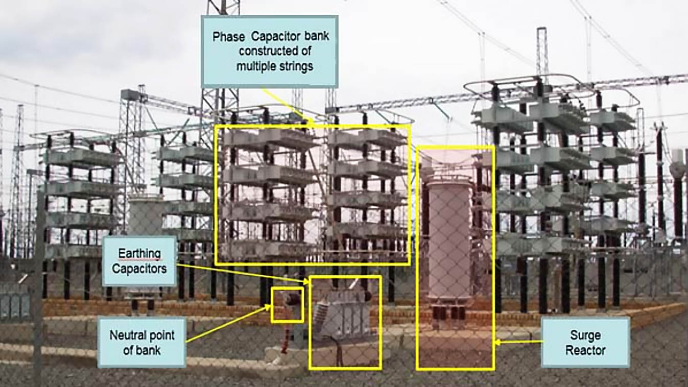
Figure 8 – 400kV 100MVAR Shunt Capacitor Bank at Hydra Substation situated in De Aar. One can see the individual capacitor elements, surge reactor and earthing capacitors respectively
Static VAR compensators (SVCs)
An SVC combines conventional capacitors and inductors with fast switching capability. Switching takes place in the sub-cycle time frame (i.e., in less than 1/60 of a second), providing a continuous range of control. The range can be designed to span from absorbing to generating reactive power.
Consequently, the controls can be designed to provide very fast and effective reactive support and voltage control. Because SVCs use capacitors, they suffer from the same degradation in reactive capability as voltage drops. They also do not have the short-term overload capability of generators and synchronous condensers.
SVC applications usually require harmonic filters to reduce the amount of harmonics injected into the power system.
Related Reading – What is the Static Var Compensator (SVC)?
Static synchronous compensators (STATCOMs)
The STATCOM is a solid-state shunt device that generates or absorbs reactive power and is one member of a family of devices known as Flexible AC Transmission System (or shorten FACTS).
The STATCOM is similar to the SVC in response speed, control capabilities, and the use of power electronics. Rather than using conventional capacitors and inductors combined with fast switches, however, the STATCOM uses power electronics to synthesize the reactive power output. Consequently, output capability is generally symmetric, providing as much capability for production as absorption.
STATCOMs are current limited so their MVAR capability responds linearly to voltage as opposed to the voltage squared relationship of SVCs and capacitors. This attribute greatly increases the usefulness of STATCOMs in preventing voltage collapse.
Figure 9 – Static synchronous compensator (Statcom) system installed in Kriftel (photo credit: Siemens)

Distributed generation
Distributing generation resources throughout the power system can have a beneficial effect if the generation has the ability to supply reactive power. Without this ability to control reactive-power output, performance of the transmission and distribution system can be degraded. Induction generators were an attractive choice for small, grid-connected generation, primarily because they are relatively inexpensive.
They do not require synchronizing and have mechanical characteristics that are appealing for some applications (wind, for example). They also absorb reactive power rather than generate it, and are not controllable. If the output from the generator fluctuates (as wind does), the reactive demand of the generator fluctuates as well, compounding voltage-control problems for the transmission system.
For gas-fired micro turbines, power electronics equipment allows them to operate at very high speeds. Photovoltaic’s generate direct current and require inverters to couple them to the power system. Energy-storage devices (e.g., batteries, flywheels, and superconducting magnetic-energy storage devices) are often distributed as well and require solid-state inverters to interface with the grid.
This increased use of a solid-state interface between the devices and the power system has the added benefit of providing full reactive-power control, similar to that of a STATCOM.
In fact, most devices do not have to be providing active power for the full range of reactive control to be available. The generation prime mover, e.g. turbine, can be out of service while the reactive component is fully functional.
This technological development (solid-state power electronics) has turned a potential problem into a benefit, allowing distributed resources to contribute to voltage control.
Related Study (PDF) – Network operating practice for efficient connection of distributed generation
Network operating practice for efficient connection of distributed generation
Transmission side
An unavoidable consequence of load operation is the presence of reactive power, associated with phase shifting between voltage and current. Some portion of this power is compensated on the customer side, while the rest is loaded onto the network. The supply contracts do not require a cosφ equal to one.
The transmission lines owner also uses the reactive power for controlling the voltages.
Reactive current component adds to the loads current and increases the voltage drops across network impedances. Adjusting the reactive power flow, the operator changes voltage drops in lines and the voltage at customer connection point. The customer’s voltage depends on everything that happens on the way from generator to customer loads. All nodes, connation points of other transmission lines, distribution station and other equipment contribute to reactive power flow.
If the transmitted power is above Sk, the line will introduce additional inductive reactive power, and if it is below Sk, the line will introduce capacitive reactive power. The value of Sk depends on the voltage: for a 400 kV line, it is about 32% of the nominal transmission power, for a 220 kV line, it is about 28%, and for a 110 kV line, it is about 22%. The percentage will vary according to construction parameters.
The reactive power introduced by the lines themselves is a nuisance for the transmission system operator. At night, when the demand is low, parallel reactors must be connected to consume the additional capacitive reactive power of the lines. Sometimes, a low-loaded line must be switched off (which definitely affects the system reliability). In peak hours, not only do the customer loads cause big voltage drops, but the inductive reactive power of the lines adds to the total power flow and causes further voltage drops.
The voltage and reactive power control has some limitations. A big part of reactive power is generated in power plant unites. The generators can deliver smoothly adjustable leading and lagging reactive power without fuel costs.
However, reactive power occupies the generation capacity and reduces active power production. Furthermore, it is not worth transmitting reactive power over a long distance (because of active power losses). Control provided “on the way” in transmission lines, connection nodes, distribution stations, and other points requires installation of capacitors or reactors.
They are often used with transformer tap-changing systems. The range of voltage control depends on their size. The control may consist, e.g., of setting the transformer voltage higher and then reducing it by reactive current flow.
If the transformer voltage reaches the highest value and all capacitors are in operation, the voltage on the customer side cannot be further increased. On the other hand, when a reduction is required, the limit is set by the maximal reactive power of reactors and the lowest tap of the transformer.
Case Study (PDF) – Adding capacitor banks to the Sri Lankan transmission network (Analysis)
Adding capacitor banks to the Sri Lankan transmission network (Analysis)
Voltage and reactive power planning and assessment practices:
1. Key Principles:
- Reactive power cannot be transmitted over a long distance or through power transformers due to excessive reactive power losses.
- Reactive power supply should be located in close proximity to its consumption.
- Sufficient static and dynamic voltage support is needed to maintain voltage levels within an acceptable range.
- Sufficient reactive power reserves must be available to regulate voltage at all time.
2. Key Implications:
- Metering must be in place and maintained to capture actual reactive consumption at various points.
- Transmission and Distribution planners must determine in advance the required type and location of reactive correction.
- Reactive power devices must be maintained and functioning properly to ensure the correct amount of reactive compensation.
- Distribution reactive loads must be fully compensated before transmission reactive compensation is considered.
3. Transmitting Reactive Power
- Reactive power cannot be effectively transmitted across long distances or through power transformers due to high I2X losses.
- Reactive power should be located in close proximity to its consumption.
4. Static vs. Dynamic Voltage Support
- The type of reactive compensation required is based on the time needed for voltage recovery.
- Static Compensation is ideal for second and minute responses. (Capacitors, reactors, tap changes).
- Dynamic Compensation is ideal for instantaneous responses. (condensers, generators)
- A proper balance of static and dynamic voltage support is needed to maintain voltage levels within an acceptable range.
5. Reactive Reserves during Varying Operating Conditions
- Ideally, the system capacitors, reactors, and condensers should be operated to supply the normal reactive load.
- As the load increases or following a contingency, additional capacitors should be switched on or reactors removed to maintain acceptable system voltages.
- The reactive capability of the generators should be largely reserved for contingencies on the EHV system or to support voltages during extreme system operating conditions.
- Load shedding schemes must be implemented if a desired voltage is unattainable thru reactive power reserves.
Suggested Reading – The art of load shedding and online applications in a power system under an emergency state
The art of load shedding and online applications in a power system under an emergency state
6. Voltage Coordination
- The reactive sources must be coordinated to ensure that adequate voltages are maintained everywhere on the interconnected system during all possible system conditions.
- Maintaining acceptable system voltages involves the coordination of sources and sinks which include:
- Plant voltage schedules
- Transformer tap settings
- Reactive device settings
- Load shedding schemes.
- The consequences of uncoordinated operations would include:
- Increased reactive power losses
- A reduction in reactive margin available for contingencies and extreme light load conditions
- Excessive switching of shunt capacitors or reactors
- Increased probability of voltage collapse conditions.
7. Voltage Schedule
- Each power plant is requested to maintain a particular voltage on the system bus to which the plant is connected.
- The assigned schedule will permit the generating unit to typically operate:
- In the middle of its reactive capability range during normal conditions
- At the high end of its reactive capability range during contingencies
- “Under excited” or absorb reactive power under extreme light load conditions.
8. Transformer Tap Settings
- Transformer taps must be coordinated with each other and with nearby generating station voltage schedules.
- The transformer taps should be selected so that secondary voltages remain below equipment limits during light load conditions.
9. Reactive Device Settings
- Capacitors on the low voltage networks should be set to switch “on” to maintain voltages during peak and contingency conditions. And
- “Off” when no longer required supporting voltage levels.
10. Load Shedding Schemes
- Load shedding schemes must be implemented as a “last resort” to maintain acceptable voltages.
11. Voltage and Reactive Power Control
- Requires the coordination work of all Transmission and Distribution disciplines.
- Transmission needs to:
- Forecast the reactive demand and required reserve margin
- Plan, engineer, and install the required type and location of reactive correction
- Maintain reactive devices for proper compensation
- Maintain meters to ensure accurate data
- Recommend the proper load shedding scheme if necessary.
- Distribution needs to:
- Fully compensate distribution loads before Transmission reactive compensation is considered
- Maintain reactive devices for proper compensation
- Maintain meters to ensure accurate data
- Install and test automatic under voltage load shedding schemes
Recommended Course – Power Engineering Course: Generators, Transformers and Transmission Lines
Power Engineering Course: Generators, Transformers and Transmission Lines
References:
- Samir Aganoviş,
- Zoran Gajiş,
- Grzegorz Blajszczak- Warsaw, Poland,
- Gianfranco Chicco
- Robert P. O’Connell-Williams Power Company
- Harry L. Terhune-American Transmission Company,
- Abraham Lomi, Fernando Alvarado, Blagoy Borissov, Laurence D. Kirsch
- Robert Thomas,
- OAK RIDGE NATIONAL LABORATORY
Related electrical guides & articles


Jignesh Parmar
Electrical Middle management professional having more than 22 years rich and dynamic experience in Project Execution / Project Management / Designing / Maintenance diversifies from Electrical Power Transmission (400KV/220KV/66KV)- Distribution(11KV/220V) to Lifts-HVAC-Ventilation-Fire Fighting-Fire Alarm-Lifts-CCTV-Stack Parking Works (High Rise Buildings, Townships, Shopping Complex, Commercial Complex, School, Temple).Profile: Jignesh Parmar

Best website for all engineers
Thanks for the really helpful article about reactive power. Question: I am trying to connect a distributed generator (17MW solar facility) to the regional distribution system. The utility has asked us to operate the facility at a suggested power factor of -0.89 (absorbing Vars) to help control system voltage. Our inverters can operate within this range. My question is will absorbing reactive power limit our facility’s real power output capability? (i.e., we are only compensated (paid) for real power delivered.) I understand that if we were asked to produce reactive power, then this would sacrifice the amount of real power delivered, but want to ensure this is not the case when absorbing Vars. Thanks in advance for any advice you can provide.
In order to connect to the distribution system your facility owner will have signed an Interconnection Agreement. That agreement will likely specify that you must agree to operate within a voltage schedule. A power factor of -.89 is rather extreme and will cost you some income from lost MWs. Most voltage schedules will make you operate between ~.97 and .99. Check and see what the IA requires. Then check and see what other IAs with the same distribution organization have specified.
They can ask you to operate at a power factor of -.89. But they should pay you for the lost opportunity costs of reducing your MW output.
A good article but it clearly needs some additional support with regards to grammar and spelling. I know the article is several years old, however, I would be happy to re-write the article so that it can be improved for the benefit of everyone. If you would like to consider this option please get in touch with me.
Great Article. Thanks you for writing.
Great article!
Excellent
I think this is the most professional looking article about ‘Reactive power’ with a lot of grammatical mistakes.
Thanks sir , very nice, V good sir
Dear Sir,
Good Day.
Your article is informative. After reading I thought to ask you for support in practical problem.
Scenario
In plant two same type of engine is installed. Control Panel Have 1020 AVR. No grid or extra source is available.
Engine-A is running normal at 5500 kW in Auto Mode, Engine-B is started, synchronized, in Manual mode increase the Load when it become nearly half of available load i.e. on 2700 kW put Engine-B also in Auto mode to share reactive power and it does, same P.f and same reactive power.
Now try to stop Engine-A, put in manual mode, reduce the load nearly 1800 kW now again put in Auto Mode but this time it releases KVAVr and Engine-B moving to word unity, similarly revers the practice then Engine-A Moving to words Unity.
Question:
is there any standard limit to share the reactive load, I mean ratio like here 1800: 3900 or it will share load at any ratio?
Question:
which Parameter/s should I see to control this problem??
Question:
I believe it is simple to equal the PTs Secondaries or slight tuning is enough ? This behavior I never seen before ?
Regards
It’s a great article really very helpful. Thank you so much.
hi
thanks MrJignesh Parmar
now im facing problem MVAr, power factor at my generation plant .one the engine problem
and thank for help.
This article will thoroughly confuse the engineers, who do not have much experience in reactive controls such as generator VAR control and/or SVC systems.
Great article
Helpful article but needs proof reading and language corrections at the top.
Excellent read.vs helpful
tell about smart grid, smart metering
hello
I information or articles about the impact of reactive power on the parameters of electric and magnetic synchronous generator want everyone can help ? ? ?
or about the impact of reactive power on regulating protective relays .
email : [email protected]
Thanks
thanke you mister
New to the wind and HV industry, this made me understand the whole Reactive Power a lot better than it was explained in University.
Much appreciated,
Thanks
sir ,
i works in iocl . my switch yard which is recieving end of uppcl that charges by the rate of kva . i want to installation of shunt capacitor so i want to know that description of capacitor bank,cost cutting , energy saving and formulae to be used our reciving end voltage is 33kv and current is 10 A. pls guide me immediately
Thank you Mr. Jignesh Parmar
sir is there any equations or relations to justify that “voltage reduces due to decrease of reactive power and vice versa”?
These papers may be helpful: (eq. 1)
1-“A review on voltage control methods for active distribution networks”
2-“Voltage control techniques for electrical distribution networks including distributed generation”
The information provided is so much useful..Landed in a best place after many trails…
Keep doing good..:)
Very useful & interesting
too good. :)
Following can said in the answer to the question “What is reactive power?”
It is power associated with the net zero energy transfer over a integer multiple of cycles of supply.
Also following is worth to note :
In case of say, induction machine, the reactive power is responsible for the magnetic field, which is the,a must medium for energy transfer. Now this field strength has to be constant so that the machine magnetic circuit do not saturate. So the magnetic field must not get any amount energy once it is fully developed. At the same time, a continuous flow of current has to be there in order to have the flux. The flux is there as long as the current flows in the stator winding. These both can happen only if the current responsible for machine magnetization, over a cycle (to be more specific even a half cycle) , do not become a tool for transfer of energy from source to machine magnetic field. So, here there is the role of reactive power.
Therefore. we can state that the machine operation is possible only if it draws reactive power from the source.
Very informative. I have some queries pls,
1. Reactive power is required by some loads, so does the utility specifically generate reactive power for that purpose? i know S=P+jQ, Does generating station produce S or P?
It produces S, wich include P and Q.
Fine.
thanks.
Hello;
first of all, the lecture is very intersting and important, thank you
But i’ve a question. you state that “Reactive power is essential to move active power through the transmission and distribution system to the customer.”
can you explain these part for me ??
Hello Tamer,
Well you can see that whatever is developed at consumers end is neglected ,you know we have different appliances with different power consumption in order to vary the voltage at users end , it is necessary to control voltage .So thats the main reason we have supply reactive power .
Is there any thumbrule for calculation of required KVAr for achieve given power factor assuming KVA constant
S for 4 hp we should take 1kvar
Thnx