
Estimated Study Time: 19 minutes
Metering and protection purpose
First, let’s remind ourselves of the basics in a few sentences. That is something you must know. A current transformer (CT) is designed to produce a secondary current which is accurately proportional to the primary current. It consists of a single primary winding, which an external busbar or cable runs through, or it can have a single primary bar, brought out to two ends for termination.
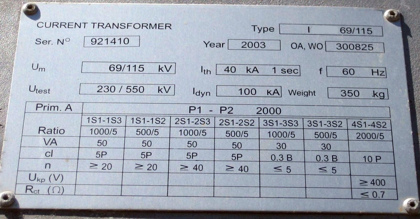
 IEC and NEMA ratings of current transformers (CTs) for a medium voltage switchgear (photo credit: Energie Technik Becker GmbH)
A medium voltage current transformer can have up to three independent secondary winding sets. The entire current transformer assembly is encapsulated in resin, inside an insulated casing. Current transformers are used for metering or protection purposes.
The accuracy class and size depends on the individual application – for example, revenue metering would use high accuracy metering CTs.
Just to note, it’s very important to never leave the secondary winding of a CT open circuit. This creates extremely high voltages which pose a real danger to personnel.
Ok, let’s get on the IEC and later NEMA ratings of a current transformer. Some rating explanations have exercises and real examples, which I hope it will help for better understanding.
- IEC ratings of current transformer
- Rated primary current
- Rated secondary current: Isr
- Transformer ratio: Kn
- Rated thermal short-time withstand current: Ith (kA)
- Overcurrent coefficient: Ksi
- Rated primary circuit voltage: Up (kV)
- Rated frequency
- Rated real output power (VA)
- Metering class CT
- Protection class CT
- Selection of current transformers
- NEMA/IEEE ratings of current transformer
1. IEC Ratings
1.1 Rated primary current: Ipr (A)
The primary current rating of a CT must be greater than the expected maximum operating current it is monitoring.
Standard values for Ipr are: 10, 12.5, 15, 20, 25, 30, 40, 50, 60, 75 A, and decimal multiples of these values (source: IEC 60044-1)
1.2 Rated secondary current: Isr
The secondary current rating of a CT is either 1 A or 5 A. CTs with a 5 A secondary rating are becoming less common as more CT driven equipment becomes digital. For long secondary cable runs, CTs with 1 A secondary windings can minimize the transformer and secondary cable size.
1.3 Transformer ratio: Kn
This is the ratio of secondary to primary winding turns: Kn = Ns/Np = Ipr/Isr
1.4 Rated thermal short-time withstand current: Ith (kA)
This is the highest level of rms primary fault current which the CT can endure, both thermally and dynamically, for 1 second without damage. When used in a medium voltage enclosure, the Ith rating should match the short-time withstand rating of the entire switchgear.
1.5 Overcurrent coefficient: Ksi
This is the ratio of a CT’s short-time withstand current rating to its primary current rating:
Ksi = Ith/Ipr
This coefficient indicates how difficult it would be to manufacture a CT. A higher coefficient means a physically larger CT, which is more difficult to manufacture.
- If Ksi < 100 it’s easy to manufacture
- If Ksi 100 ~ 500 it’s difficult to manufacture, with certain limitations
- If Ksi > 500 it’s extremely difficult to manufacture
1.6 Rated primary circuit voltage: Up (kV)
The primary circuit voltage rating indicates the level on insulation provided by the CT. If a ring type CT is installed around a cable or bushing, the insulation level can be provided by the cable or bushing.
| Rated primary voltage Upr (kV) | Suitable operation range U (kV) | Power frequency withstand voltage (kV) rms for 1 minute | Lightning impulse withstand voltage (kV) peak, 1.2/50μs |
| 7.2 | 33-7.2 | 20 | 60 |
| 12 | 6-12 | 28 | 75 |
| 17.5 | 10-17.5 | 38 | 95 |
| 24 | 12-24 | 50 | 125 |
| 36 | 20-36 | 70 | 170 |
Source: IEC 62271-1
1.7 Rated frequency: fr (Hz)
This rating must match the system’s operating frequency. Standard frequencies are 50 Hz and 60 Hz. It’s very important to be cautios, because a 50 Hz CT can be used on a 60 Hz system, but a 60 Hz CT cannot be used on a 50 Hz system.
1.8 Rated real output power (VA)
The maximum power a CT secondary can deliver, to guarantee its accuracy and performance. The total sum VA (including cable, connectors and load) must not exceed the rated real output power of the CT. Standard values are: 1, 2.5, 5, 10, 15 VA.
Cable burden can be calculated the following way: VAcable = k × L/S, where:
- k = 0.44 for 5 A secondary, = 0.0176 for 1 A secondary
- L = total feed/return length of cable (m)
- S = cross sectional area of copper cable (mm2)
Metering instrument burden:
- Metering instrument (digital) = 1 VA (approx.)
- Metering instrument (electromagnetic or induction) = 3 VA (approx.)
- Transducer (self powered) = 3 VA (approx.)
Protection instrument burden:
- Protection instrument (digital) = 1 VA (approx.)
- Protection instrument (electromagnetic overcurrent) = 3-10 VA (approx.)

1.8.1 Exercises
Exercise #1 – A CT with a 1 A secondary is connected to an electromagnetic ammeter located 10 m away, using 2.5 mm2 copper cable.
Calculate the minimum required VA rating of the CT.
- VAcable = k × L/S = 0.0176 × 20/2.5 = 0.14 VA
- VAammeter = 3 VA
- VAtotal = 0.14 + 3 = 3.14 VA
The total burden is 3.14 VA. Use a 5 VA CT.
Exercise #2 – A CT with a 5 A secondary is connected to a digital protection relay located 2 m away, using 1.5 mm2 copper cable.
Calculate the minimum required VA rating of the CT.
- VAcable = k × L/S = 0.44 × 4/1.5 = 1.17 VA
- VAammeter = 1 VA
- VAtotal = 1.17 + 1 = 2.17 VA
The total burden is 2.17 VA. Use a 2.5 VA CT.
1.9 Metering class
A metering class indicates the accuracy of the CT secondary current at 5 to 125% of rated primary current. Above this level, the CT starts to saturate and the secondary current is clipped to protect the inputs of a connected metering instrument.
- General metering CT would use a metering class CL 0.5 – 1.0
- Revenue metering CT would use a metering class CL 0.2 – 0.5

Where:
- Saturation
- Linear operating range, at accuracy class tolerance
1.10 Protection class CT
A protection class CT provides a linear transformation of the primary to secondary current at high overload levels. This characteristic makes them suitable for use with overcurrent protection relays.
A relay trip setting is normally 10~15 times the maximum load current and this level should fall on the linear part of the CT secondary current curve. If a CT saturates before the relay trip level is reached, the fault will remain undetected, leading to equipment damage and serious danger to personnel.
Typical protection class CT ratings are 5P10, 5P15, 5P20.

Where:
- Saturation
- Linear operating range, at accuracy class tolerance
- Ideal protection setting trip zone 50%~100% ALF
1.10.1 Example
A 200/1 A CT has a protection class rating of 5P15. The secondary current is guaranteed to be linear up to 15 times the rated primary current. The secondary current will be 1 A (+/-1%) at 200 A primary current and 15 A (+/-5%) at 3000 A primary current.
For guaranteed operation, any overcurrent trip setting should be between 7.5 ~ 15 A secondary current.
1.11 Selection of current transformers
The main considerations for selecting a CT are the primary and secondary current ratio, real output power rating (VA) and accuracy class. Secondary selection considerations are rated primary voltage, frequency and thermal short-time withstand current.
1.11.1 Primary and secondary current ratio
Rated primary current: Ipr (A)
| Source | Rated primary current Ipr (A) |
| Incomer from transformer | Ipr ≥ 1.0-1.25 of nominal source current |
| Feeder to transformer | Ipr ≥ 1.0-1.25 of transformer’s rated primary current |
| Feeder to motor | Ipr ≥ 1.0-1.5 of motor full load current |
| Feeder to capacitor bank | Ipr ≥ 1.3-1.5 of nominal capacitor current |
Rated secondary current: Isr (A)
- Use 1 A and 5 A for local installation
- Use 1 A for remote installation
1.11.2 Real output power (VA)
The real output rating of the CT must be the next highest nominal size above the expected total burden on the CT secondary. Total burden is the sum of output cable, connectors and instruments.
1.11.3 Class type
Use a metering class CT for metering and indication. A higher class CT gives greater accuracy between the primary and secondary currents.
1.11.4 Exercise
Select appropriate CTs for the following transformer incomer and feeder circuits.

Where:
1. Transformer Incomer:
- MV/MV transformer (TXR1): 5 MVA, 36/11 kV, 10% Z
- Instantaneous overcurrent trip setting = 15 × In for digital protection relay (OC1) driven off CT1-2
- Electromagnetic ammeter (A) is driven off CT1-1
2.Transformer Feeder:
- MV/LV transformer (TXR2): 2 MVA, 11/0.4 kV, 5% Z
- Instantaneous overcurrent trip setting = 10 × In for digital protection relay (OC2) driven off CT2
Exercise 1 – Metering CT1-1 for transformer incomer circuit:
Step 1 – Calculate transformer TXR1 nominal secondary current: In (A)
- In = S/(√3 × U) = 5000/(√3 × 11) = 262 A
- The secondary current for TXR1 is 262 A
Step 2 – Calculated max. expected short circuit current at CT1 installation: Isc (A)
- Ignoring any power cable or busbar impedances:
- Isc = In × 100/Z = 262 × 100/10 = 2620 A
- The maximum expected short circuit current at CT1 is 2620 A
Step 3 – Select metering CT1-1 ratings:
- Primary rated current: Ipr = (1.0-1.25) × In = (1.0-1.25) × 262 A
Use a rating of 300 A
- Secondary rated current: Isr
Use a rating of 1 A
- Short-time withstand rating: Ith ≥ Isc
Use a rating of 10 kA
- Primary circuit voltage: Up ≥ U
Use a rating of 12 kV
- Real output power: Typically > 3 VA for electromagnetic type meter
Use 5 VA (this allows 2 VA for cable burden, etc.)
- Accuracy Class
Use Class 1.0 (common class for general metering)
Exercise 2 – Protection CT1-2 for transformer incomer circuit:
Step 1 – Select ratings common to both the metering and protection CTs
- Primary/secondary rated current: Use 300/1 A
- Short-time withstand rating [Ith]: Use 10 kA rating
- Primary circuit voltage [Up]: Use 12 kV rating
Step 2 – Select real output power
- Real output power: typically > 1VA for digital type protection relay
- Use 2.5 VA (this allows 1.5 VA for cable burden, etc.)
Step 3 – Calculate protection class 5PX
- The instantaneous trip current level of protection relay OC1 is set to 15 × In.
- ITRIP = 15 × 262 = 3930 A (primary current)
Note: In most digital protection relays, the trip current levels are set with respect to the secondary current. In this case
- ISEC = 3900/300 × 1 = 13.1 A
- The instantaneous trip current level for the CT secondary is 13.1 A
The trip current level should fall between 100 to 50% of the accuracy limit factor (ALF). Using an ALF of 10 (5P10), the trip current level of 3930 A falls outside the range 100% to 50% ALF, so a 5P10 protection class CT is not suitable.
- 100%(ALF) = 1.0 × 10 × 300 = 3000 A
- 50%(ALF) = 0.5 × 10 × 300 = 1500 A
We may notice that 1500 ≤ 3930 ≥ 3000 A. Using an ALF of 15 (5P15), the trip current level of 3930 A falls within the range 100% to 50% ALF so a 5P15 protection class CT is suitable.
- 100%(ALF) = 1.0 × 15 × 300 = 4500 A
- 50%(ALF) = 0.5 × 15 × 300 = 2250 A
We may notice that 2250 ≤ 3930 ≤ 4500 A. Use protection class 5P15
Exercise 3 – Protection CT2 for transformer feeder circuit:
Step 1 – Calculate transformer TXR2 nominal primary current: In (A)
- In = S/(√3 × U) = 2000/(√3 × 11) = 105 A
- The primary current for TXR2 is 105 A
Step 2 – Calculated maximum expected short circuit current at CT2 installation: Isc (A)
- Ignoring any power cable or busbar impedances
- Isc = In × 100/Z = 105 × 100/5 = 2100 A
- The maximum expected short circuit current at CT2 is 2100 A
Step 3 – Select protection CT2 ratings
- Primary rated current Ipr = (1.0 – 1.25) × In = (1.0 – 1.25) × 105
Use a rating of 150 A
- Secondary rated current Isr
Use a rating of 1 A
- Short-time withstand rating, Ith ≥ Isc
Use a rating of 10 kA
- Primary circuit voltage Up ≥ U
Use a ratings of 12 kV
- Real output power: Typically > 1 VA for digital type protection relay.
Use 2.5 VA (this allows 1.5 VA for cable burden, etc.)
Step 4 – Calculate protection class 5PX
- The instantaneous trip current level of protection relay OC2 is set to 10 × In
- ITRIP = 10 × 105 = 1050 A (primary current)
Note: In most digital protection relays, the trip current levels are set with respect to the secondary current. In this case
- ISEC = 3900/300 × 1 = 13.1 A
- The instantaneous trip current level for the CT secondary is 7 A
The trip current level should fall between 100 to 50% of the accuracy limit factor (ALF). Using an ALF of 10 (5P10), the trip current level of 1050 A falls within the range of 100% to 50% ALF so a 5P10 protection class CT is suitable.
- 100%(ALF) = 1.0 × 10 × 150 = 1500 A
- 50%(ALF) = 0.5 × 10 × 150 = 750 A
- We may notice that 750 ≤ 1050 ≤ 1500 A
- Use protection class 5P10
2. NEMA/IEEE Ratings
These ratings are typically used for current transformers manufactured or used in North American installations. As well as a stated primary to secondary nominal current ratio, the device also carries an overall accuracy rating in the format.
AC-CR-BU
Where:
- AC = accuracy class
- CR = class rating
- BU = maximum burden (ohms)
2.1 Accuracy class
Designates the accuracy of the secondary current with respect to the primary rated current. This accuracy is only guaranteed provided the maximum burden is not exceeded.
| Accuracy class | Tolerance at 100% primary current |
| 1.2 | ±1.2 % |
| 0.6 | ±0.6 % |
| 0.5 | ±0.5 % |
| 0.3 | ±0.3 % |
2.2 Class rating
Designates the intended application of the device.
- B = for metering applications
- H = for protection applications. The CT secondary accuracy is guaranteed at 5 to 20 times the nominal primary rated current
2.3 Burden
The maximum load allowed to be connected to the current transformer secondary, to guarantee the accuracy class. The maximum burden includes secondary cable/wire, connectors and the load.
The following table converts burden in ohms to VA, for a 5 A secondary.
| Ω | 0.04 | 0.06 | 0.08 | 0.12 | 0.16 | 0.20 | 0.24 | 0.28 | 0.32 | 0.36 | 0.40 | 0.48 | 0.56 | 0.64 | 0.72 | 0.80 |
| VA | 1 | 1.5 | 2 | 3 | 4 | 5 | 6 | 7 | 8 | 9 | 10 | 12 | 14 | 16 | 18 | 20 |
tabela
2.4 Examples
0.5-B-0.1
This example indicates a current transformer with an accuracy of ±0.5%, and a maximum allowable secondary burden of 0.1 Ω (or 2.5 VA on a 5 A secondary CT). This is a metering class rated current transformer.
1.2-H-0.2
This example indicates a current transformer with an accuracy of ±1.2%, and a maximum allowable secondary burden of 0.2 Ω (or 5 VA on a 5 A secondary CT). This is a protection class rated current transformer.
Sources:
- Medium Voltage Application Guide by Aucom
- Electric Power Substations Engineering By James C. Burke
- Selection of current transformers and wire sizing in substations – Sethuraman Ganesan; ABB Inc.
Related electrical guides & articles


Edvard Csanyi
Hi, I'm an electrical engineer, programmer and founder of EEP - Electrical Engineering Portal. I worked twelve years at Schneider Electric in the position of technical support for low- and medium-voltage projects and the design of busbar trunking systems.I'm highly specialized in the design of LV/MV switchgear and low-voltage, high-power busbar trunking (<6300A) in substations, commercial buildings and industry facilities. I'm also a professional in AutoCAD programming.
Profile: Edvard Csanyi

With reference to the following statement “The primary circuit voltage rating indicates the level on insulation provided by the CT. If a ring type CT is installed around a cable or bushing, the insulation level can be provided by the cable or bushing.”. Where in IEC 62271-1 can I find this statement? Would this also apply to flexible current probes, I.e. Rogowski colis?
Excellent concepts so far as ac current metering & revenue metering is concerned at power frequencies. I established the National Primary Standards at NPL, Delhi, India for CTs and PTs.
good material
Very nice and interesting topic.
Can we use IEEE based C800 current transformer to connect Tariff metering ?
Very informative
Many thanks
Satisfactory
Which standard is used for the insulation resistance test?
Hello
Is it possible to use a 10VA CT with 1500 m copper cable and 1VA digital ammeter?
Our cross section could be 2.5 mm2 or 4 mm2.
Thank you it is really very good.
thanks again.
Hello Guys,
Woul someone please explain me the relation between burden and accuracy class of CTs? And as far as I know, you should provide the secondary burden at least 25 % of nominal ratings burden written on the CTs plate. If yes, what is the reference for this information? can you give me a link or standart name or etc.
to illustrate my question better..;
for example on a CT’s plate it is written that: metering terminal burden 10 VA;
So I need to install and use longer cable to ensure my secondary load (burden) to be higher than 25 % of 10 VA = 2,5 VA.. so .
what do you think about this application? right or wrong?
if right can you show me the reference to do so??
Thank you so much? I’m looking forward to hearing from you..
We confront this problem frequently while installing electrical meter circuit in substations. and we use very long cables without knowing whether the information atrribute something on a IEC standarts or anyplace??
okey thanks again..
urgent answer please!!!
The “actual accuracy limit factor Fa” must be calculated according to this formula:
Fa= Fn((Sin+Sn)/(Sin +Sa)), where Fn is the rated accuracy limited factor, e.g. for 5P20 20 is Fn, Sin is the internal burden of CT secondary coil, Sn is the rated burden of the CT. Sa is the actual burden of CT on the secondary side. All these values are calculated in VA by ignoring the cosphi.
This calculated Fa must be less than 5 for CT measurement, and above 10 for CT protection type. It might be the reason behind your increase in the length of cable.
Hi Rodney Hughes,
After reading the link as well as read your explanation above, I can know that using CTs of 1 A is better than CTs of 5 A nowadays because of using numerical relays today.
Thanks a lot !
A couple of things wrong with the article.
First about CT shorting. If there are multiple secondary windings on the same core, as long as one pair of terminals are connected or shorted, the other terminals MUST be left open
Refer https://ideology.atlassian.net/l/c/Zka2eGRo
Protection trip settings are NOT 10-15x rated.
Trip is generally ~120% of rated (give or take according to requirements).
There are “high-set” instantaneous elements which are set at such multiples, but it depends on grading requirements and maximum fault currents at the downstream protection devices.
Dear sir ,
Would you please explain the in case of
CT , class = PS (Differencial Protection).
Why do we recommend replacing the 6(six) NOS CT (3 for income & 3 for outgoing)?
Where RCT (secondary winding resistance ) & Vk (knee point voltage) has to be the identically same?
What is the basic method to cheek the knee point voltage, and how to identify the saturation level, & what amount of voltage should be applied, where no systems voltage is mentioned on the nameplate? I would be much obliged if you kindly let me know through my mail.
With regards,
Sukanta Dey
Hi Sukanta
PS is an old class designation .. now PX
Diff applications need the CTs to all behave the same way for all through current conditions (load or external fault) so that there is no “false differential” created in the secondary for the same primary current .. hence class PX because we are looking for the same behaviour, i.e. same volts v excitation current on the mag curve. We don’t really care how saturated they may become, as long as they both become saturated to the same extent keeping false differential very low.
P class only specifies what you can connect to the CTs to stay within accuracy, whereas PX effectively specifies how it is constructed and how it performs.
refer https://ideology.atlassian.net/l/c/Gn6YA1jq
https://ideology.atlassian.net/l/c/u9EHnAPu
and https://ideology.atlassian.net/l/c/hxGebPK0
Hello,
We installed the CT as below:
MCC Bucket feeding pump motor then, the current in MCC is showing 37 A, while the analog Ammeter at the field near the pump shows very low reading, the CT is 100:5, the analog Ammeter is range 0 to 100, and it is 100:5, 2 VA. , The motor full load current is 53.2 A. . . It is in the local control station (LCS) near the motor which both are around 500 meters away from the substation the cable is directly buried. The CT is in the MCC Bucket in the substation. But the Ammeter is not reading
Kindly advice on above-mentioned case,
Can you explain for me this:
Why do we use 1 A (Isr of CT) for remote installation instead of 5 A ?
Thanks a lot !
@ Dang Tuan Khanh
re 1 A vs 5 A …
a useful reference is
https://www.linkedin.com/pulse/current-transformers-secondary-rating-1a-5a-what-choose-sivakumar-k/
@Dang Tuan Khanh
I have been thinking further about your query re choosing 1 A or 5 A CTs.
The link I posted earlier is useful … but I think it is a bit misleading as well, and doesn’t “hit the mark” with the real reason we stopped using 5 A CTs
I also don’t agree with that author’s statement
“ALL BOARD MOUNTED CTs SHALL BE WITH A 5A SECONDARY CURRENT
and
ALL YARD MOUNTED CTs SHALL BE WITH A 1A SECONDARY CURRENT”.
That is not the reason at all!!
So I have gone back to my earliest days in protection engineering … it is an issue associated with the burden presented and hence minimum kneepoint requirements for CDG induction disc relays.
Suffice to say a 5 A CDG11 OC+EF scheme 100 m between relay and CT would require minimim kneepoint 414 V
The same using 1 A CTs would require minimum 1299 V
5 A CTs with just 5 m distance would require 273 V, whilst 1 A requires 1271 V
So 1 A was not a good proposition for electromechanical relays.
But when electronic relays came along such as MCGG
5 A CTs 100 m requires min kneepoint 153 V (0.765 V/Turn)
1 A CTs 100 m requires min kneepoint 31 V (0.031 V/Turn)
5 A CTs 5 m requires min kneepoint 12 V (0.060 V/Turn)
1 A CTs 5 m requires min kneepoint 3 V (0.003 V/Turn)
So as you can see, it is almost irrelevant choice for electronic relays.
But when you then look at Volts per Turn, we are now considering the physical construction of the CT itself.
A lower Volt per Turn means lower cross sectional area of the CT core.
So a 1 A CT is less iron, although 5 x the turns and length of wire … and in theory we could get away with thinner wire. Hence we would expect to be cheaper and less weight to mount.👍👌✨
Its all a bit difficult to explain step-by-step, but I have given it a good shake here:
https://ideology.atlassian.net/l/c/H8vU0VoU
I hope it helps
Primary rated current Ipr for CT2 = (1.0 – 1.25) × In = (1.0 – 1.25) × 105
This gives a value between 105A and 131.25A. Kindly help me understand why you used 150A for Ipr
Selected next standard size for CT
@Geoffrey Okyere Broni
Sometimes selections and settings seem a bit “arbitrary” .. it is the skill of the engineer in taking into account ALL the influencing factors.
Yes, in this case a 2 MVA transformer would have 105 A rated current at 11 kV.
The standard primary ratings are as stated multiples of 10, 12.5, 15 etc
So you probably should not choose 100 A rated primary as then you are already setting the relay above 105% of rated CT
It could be possible to choose therefore a 125 A primary rated CT as 119% of TF 105 A rated current, i.e. your protection has to be set > 105/125 = 84% of relay rated current
Choosing 150 A rated primary is 143% of 105 A, and your relay setting has to be >70% of relay rated current
Really practical information, really like
Please mail wright up on MV/LV Switchgears Panel Designing.
I’m md shariful islam I’m working qatar MHM- al muftah company