
Incorrectly specified CT?
When a CT manufacturer says that he is unable to manufacture the requested CT, nine times out of ten this is because the CT has been incorrectly specified. To eliminate all the cumulated safety margins taken by all the people involved, the CT must be redefined on the basis of real needs: real currents in the installation, types of protection, required power, and discrimination study and protection plan (settings).
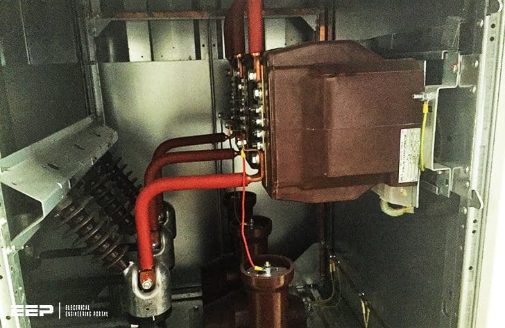 Have you experienced an incorrectly specified CT that can't be manufactured? (photo credit: EEP)
This approach must be adopted whenever the specification leads to a non standard CT. Costs, lead times and safety are the factors at stake.
Let us take an example:
We have calculated the class X of a 1000/5 CT for a generator differential protection, assuming that X’’ = 15 %. Not knowing the exact characteristics of the generator, we have assumed that the generator In equals the CT In .
This results in If = 100/15 × In of the CT i.e. Vk ≥ 2 × 6.7 × 5 (Rct + 2 RL)
We have rounded off 6.7 as 7. Then we assumed:
2 RL = 300 m of 2.5 mm2, i.e. 2.4 Ω hence: Vk ≥ 70 Rct + 168.
Then:
- 2 RL = 1.5 Ω
- Generator In = 830 A.
- X’’ = 25 %, hence:
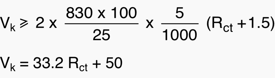
The difference is marked and shows the importance of obtaining the right information and of knowing the safety margins.
If the CT is declared impossible to manufacture, a solution, i.e. a compromise, must be found between all those involved. There is always a way out, which can be found with the help of specialists.
As an example, here are a few leads:
- Play on the equivalences between CTs,
- Reduce the safety coefficient (for instance 2 to 1.5 for an overcurrent protection),
- Change the secondary from 5 to 1 A (see table 1), c increase wiring cross-section,
- Overrate the CTs (primary In),
- Move the relay with respect to the CT,
- Use matching CTs with low consumption,
- and so on…
Table 1 – Losses in wiring for a 2.5 mm2 cross-section (8 Ω/km at 20° C). With 1 A, losses are 25 times less.
| Length (m) | 5 | 10 | 20 | 50 | 100 | 200 | 400 |
| Wiring losses (VA) for: | |||||||
| In = 1 A | 0.04 | 0.08 | 0.16 | 0.4 | 0.8 | 1.6 | 3.2 |
| In = 5 A | 1 | 2 | 4 | 10 | 20 | 40 | 80 |
The overrating of a CT can solve a manufacturing problem
Let us take two examples:
Example #1 – A 100/1 CT with a load of 2.5 VA requires an ALF of 25 for an overcurrent protection.
The standard CTs proposed are 2.5 VA-5P20. If a CT with a ratio of 150/1 – 2.5 VA-5P20 is proposed, the accuracy limit factor (ALF) need will be reduced in the CT primary ratio, i.e. necessary
If the class X requested for a CT is proportional to a through current or a primary Isc, these values are multiplied by the CT ratio. Thus, the required knee point voltage will be less for an overrated CT, unless its increasing resistance Rct starts to neutralise the ratio benefit.
In all cases, it will be possible to create a higher knee point voltage than with a CT of lower ratio, as it is proportional to the number of secondary turns.
Indeed, the space required for the number of turns x 5 results in reduction in wiring cross- section, thus naturally increasing its linear resistance. The new resistance can thus be amply multiplied by 10 with respect to the 5 A CT.
Example #2 – If you are tempted to impose a CT overrating, you must check the repercussions of the change in ratio.
For example:
- If the CT supplies a pilot wire differential protection, you must ensure that the corresponding CT at the other end of the line has also the same ratio change.
- In the case of a restricted earth protection, you must ensure that:
- the CT installed on the neutral point is also modified,
- the earth fault detection is not compromised by the overrating.
- For all protection types, you must check that setting of the protection is still possible.
Optimisation of the differential protection CTs
Let us take the example of a transformer differential protection (see figure 1).

Calculating the through current
The transformer impedance limits the through current to:
Short-circuit power becomes:
The through current at the secondary is:
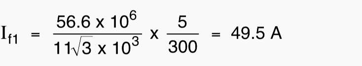
at 11 kV side:
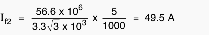
at 3.3 kV side:
Formulas to be applied for Vk (standard protection):
Calculating the matching CTs with a ratio of 5/(5/√3):

Calculating main CTs:
at 11 kV side: 300/5

at 3.3 kV side: 1000/5
![]()
Optimisation approach
Let us examine the case of the 300/5 CT placed in the 11 kV switchboard.
First hypothesis
The matching 5/(5/√3) is the one proposed as standard by the relay manufacturer. It is located with the relay on the 3.3 kV side. Wiring is 2.5 mm2 throughout.
- RL1 = 4 Ω
- RL2 = 0.08 Ω
- RL3 = 0.024 Ω
- R = 0.25 Ω, secondary winding resistance of the matching CT,
- Rsp = 0.15 Ω, primary winding resistance of the matching CT,
- Rp = 0.02 Ω, relay resistance.
We find:
- Vka mini = 43.7 V (standard Vka = 58 V),
- Vkp1 mini = 198 Rct + 847
Second hypothesis
The same as the first, except that RL1 wiring is in 10 mm2, hence RL1=1 Ω
The result is:
Vkp1 mini = 198 Rct + 243
Third hypothesis
The matching CT is on the 11 kV side as well as the relay: RL1 = 0.08 Ω
Vkp1 mini = 198 Rct + 61
Fourth hypothesis
Same as the third hypothesis, except for the matching CT which is not standard, but which is imposed on the CT manufacturer where:
Rs ≤ 0.1 Ω,
Rp ≤ 0.1 Ω,
which results in:
Vka mini = 26.5 V
Vkp1 mini = 198 Rct + 41
The same approach adopted for the 1000/5 CT, placed on the 3.3 kV side, yields results that are fairly similar concerning Vk.
However, in view of the fact that a 1000/5 CT is easier to manufacture than a 300/5 CT, it is more advantageous to place the relay and the matching CT on the 11 kV side. If a 1 A CT is used, the same hypotheses as above enable a move from:
Vkp1 = 39.6 Rct + 249 to Vkp1 = 39.6 Rct + 17
The 1 A CTs may be easier to manufacture than the 5 A CTs, but all depends on the relative weight of the Rct and the wiring in the Vk expression.
Reference // Current transformers: specification errors and solutions by Paola FONTI (Schneider Electric)
Related electrical guides & articles


Edvard Csanyi
Hi, I'm an electrical engineer, programmer and founder of EEP - Electrical Engineering Portal. I worked twelve years at Schneider Electric in the position of technical support for low- and medium-voltage projects and the design of busbar trunking systems.I'm highly specialized in the design of LV/MV switchgear and low-voltage, high-power busbar trunking (<6300A) in substations, commercial buildings and industry facilities. I'm also a professional in AutoCAD programming.
Profile: Edvard Csanyi

Can we use CT for differential protection, but the CTs are different ALF? The CT has the same class 5P20 and the other one 5P30. Both CTs are 600/5 Amp.
Why in PS class CT Imag current is specified at Vk/2 ?
What do you think to do business in the World’s fastest growing country INDIA?? It will be my pleasure to be working with you & your extra ordinary ideas
شكرا اعجبنى كثيرا ارجو التواصل