Conductors close to one another
Cabling in power substations is very important due to the fact that they are the longest parts of a system and therefore act as efficient antennas that pickup and or radiate noise. In HV substations, there are different kinds of conductors close to one another, such as high voltage buses, CTs, VTs, carrier couplers, bushing, control cables, substation ground conductors, and equipment ground connections.

The control cables are used to carry potential transformer outputs, current transformer outputs, circuit breaker control signals, relaying, and other communication signals. Increasingly, electronic equipment is used in switchyards and control houses.
The induced voltage produced inside a substation can couple into low voltage control cables and electronic equipment unless it is suitably protected. Parallel conductors exhibit both mutual inductance and capacitance.
In addition, if care is not taken to ground the system properly, ground currents at these frequencies may be coupled with the instrumentation and control system resistively, capacitively, or inductively, producing nuisance trips.
This technical article presents the induced voltages in the control cables due to switching and lightning surges. In the presence of shunt capacitor banks in the substation, the magnitude and frequency of the switching surges increase.
1. Sources of induced voltages
1.1 Resistive coupling
Resistive coupling is noise transmitted electrically through a common ground impedance path. Substation should not use common ground impedance path for MV/HV cables and control/signal cables.
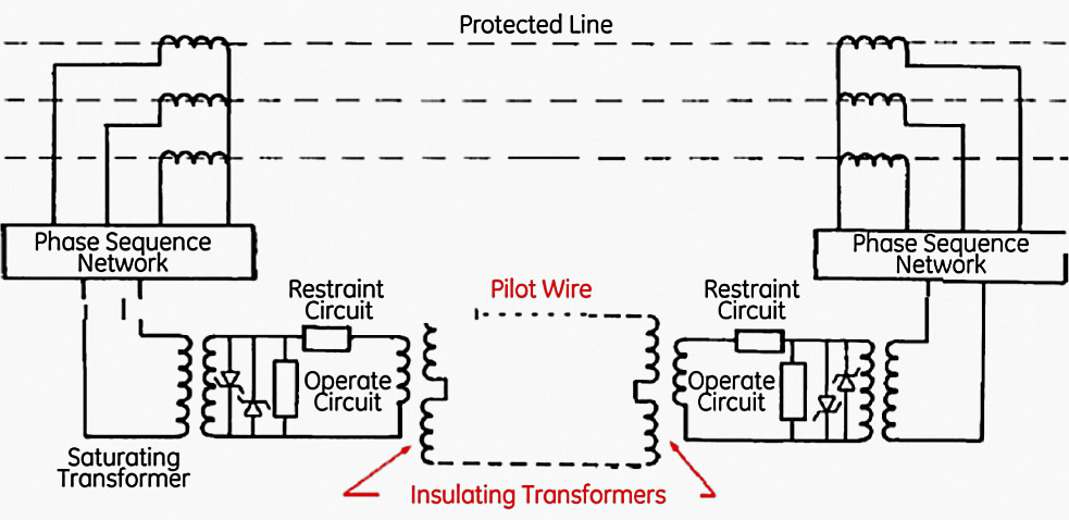
Isolation transformers may also have to be provided to guard against rises in substation ground potential due to earth faults.

1.2 Capacitive coupling
As the name suggests, capacitive coupling is the coupling of noise currents via stray capacitance. From basic circuit theory we know that capacitance (C) is related to area (A) and distance (d) in the following manner:
C = εA/d
That is to say, capacitance increases as area is increased, and decreases as distance is increased. The easiest thing to do then is to keep the cables separated from one another. Generally only small attenuation is gained by spacing the conductors at a distance greater than 40 times their diameter.
The capacitance acts as a voltage divider. During transient switching operations, there will be induced currents in the control cable, given by the following equation:
i = C × dV/dt
Increased distance between the power conductor and the control cable can reduce the induced voltage in the control cable.


1.3 Inductive Coupling
The presence of a power conductor close to a control cable can produce inductive coupling between the two. The current through the power conductor produces magnetic flux as shown in Figure 3. If a control cable is present in the magnetic field, then there will be induced voltage at the power frequency.
The magnitude of the induced voltage depends on the mutual coupling between the conductors and the current through the conductor. The induced voltage in the control cable is given by:
e (control cable) = M × di/dt
where:
- M is the mutual inductance between the power conductor and the control cable and
- i is the current through the conductor.
The electric field is proportional to the charge per unit length r on the bus and is inversely proportional to the shortest distance r between the field point on the bus given by:
E = ρ / 2πεsr
ρ = CVph
C = 1 / (Zs × c)


Where:
- c = Velocity of light = 3 × 10⁸ m/s
- C = Capacitance of the bus
- Vph = Voltage per phase
- Zs = Surge impedance, Ω/phase
Re-arranging the above equations:
E = (377 × Vph) / 2πZsh
where
η = √(μ0/ε0) = 1/ε0c = 377 Ω
The radius r is equal to the bus height h. The vertical electric field is doubled upon reflection from the ground. For 1.0 per unit switching transients, the electric field is given by:
E = (377 × Vph) / πZsh
1.3.1 Example
Calculate the electric field at a distance of 8 m from the phase conductor of a 230 kV system. Assume a surge impedance of 350 Ω/phase.
Solution
- h = 8 m,
- Zs = 350 Ω/phase
- System line-to-line voltage = 230 kV
- Phase voltage (230 kV/1.732) = 132.8 kV
E = (377 Ω) (132.8 kV) / π (350 Ω) (8 m) = 5.7 kV/m
1.4 Switching transients due to circuit breaker operations
The moving contacts of the circuit breakers not only allow multiple breakdowns of the insulating medium between the components of the high voltage system, but also allow the breakdown potentials to exceed the system operating voltage due to trapped charges.
The oscillation frequencies may vary from the nominal supply frequency to several kHz. When control cables are present, there will be induced voltages due to mutual coupling.
1.5 Lightning Transients
Lightning strikes can also cause arcing in substation equipment and produce transients. When control cables are laid in parallel to the power line conductors transmitting such transients there will be induced voltages.
In a substation, the induced voltages in the control cables may be due to conducted coupling, radiated coupling such as electrostatic coupling, or inductive coupling.
The induced voltage through the control cables can cause damage to electronic equipment.


2. Acceptable induced voltages
The acceptable induced voltages in control cables are adopted from IEC 61000-4-4 due to fast electrical transients. The following four levels of environmental conditions are identified:
- Level 1 – Well protected
- Level 2 – Protected
- Level 3 – Typical industrial
- Level 4 – Severe industrial
Table 1 – Severity and Acceptable Induced Voltage Levels
| Level | On power supply | On signal and control cable | ||
| Voc kV | Isc A | Voc kV | Isc A | |
| 1 | 0.5 | 10 | 0.25 | 5 |
| 2 | 1.0 | 20 | 0.50 | 10 |
| 3 | 2.0 | 40 | 1.00 | 20 |
| 4 | 4.0 | 80 | 2.00 | 40 |
The acceptable peak amplitudes for various severity levels are presented in Table 1. The open circuit voltage for each severity level for both the power supplies and data lines are given in Table 1.
The short-circuit values are estimated by dividing the open circuit voltage by 50 Ω source impedance. This value represents the worst-case voltage seen by the surge suppression element.
The acceptable induced open circuit voltage in data lines is 2 kV.
2.1 Example of 230kV and 115kV substations
The 230 kV and the 115 kV substation used in this study is operated with the entire cross-bays closed. The substation uses a one and a half circuit breaker scheme with double bus system. The 60 MVAR capacitor bank is connected to the 230 kV system.
The specifications of the capacitor bank are:
- Nominal system voltage = 230 kV
- Maximum system voltage = 253 kV (+10%)
- Rating of capacitor bank at 230 kV = 60 MVAR
- Frequency = 60 Hz
- Connection = Grounded wye
2.1.1 Circuit Breaker for Capacitance Switching


- Maximum voltage = 242 kV
- Interrupting current = 40 kA
- Continuous current = 3,000 A
- BIL level= 1,050 kV
- Bus diameter = 12.5 cm
- Diameter of the control cable = 0.8 cm
- Diameter of the shield = 0.3 cm
The 230 kV and 115 kV circuit breakers along with the 60 MVAR capacitor banks are shown in Figure 5. The electromagnetic interference was suspected to be responsible for equipment failure or nuisance tripping in the other 115 kV power factor capacitor installation project within the utility.
A study was performed to identify the related issues and apply suitable mitigation measures. The induced voltages in the control cables can emanate in a substation due to the switching operations (energizing, de-energizing, reclosing, fault clearing, backup fault clearing) and lightning strikes.
Sources:
- Power System Capacitors by Ramasamy Natarajan
- Cahier technique no. 149; EMC: electromagnetic compatibility by Schneider Electric
- EMC- What’s all the Noise about by By Craig Dunne NHP Electrical Engineering Products Pty Ltd Development Engineer








We are also facing the problem of induced voltage in 230V AC, 250 to 500 Meters long control cables. We see up to 128V which causes nescience to smart relays having threshold of 84V. Power Supply Lines are of 440V AC or 6.6 KV in some places. Power and control cable separation has been done but no significant results achieved. Can you suggest any significant and viable solution ?
Thanks a lot for sharing this valuable article. Very useful information regarding induced voltages.
Thanks a lot for sharing this technical and valuable article.
Nuisance tripping and noise are likely even in low voltage applications, as in offshore rigs.
In that sense, power cables, even at voltage levels of 480 V or 440 V (motor loads), shall run with sufficient clearance, typically 300 mm, from Instrumentation and Telecommunication cables.
Thanks a lot for sharing this valuable article.
very useful article
Articles, documents are very good and useful
I want to have membership in your portal but it is little expensive to me
if available give some discount to make it easier for me and others to subscribe
Best regards