Content
1. Visual and Mechanical Inspection
1. Compare equipment nameplate datawith drawings and specifications.
2. Inspect physical and mechanical condition of busway system
3. Inspect anchorage, alignment, and grounding.
4. Verify correct connection in accordance with single-line diagram.
5. Inspect bolted electrical connections for high resistance using one or more of the following methods:
- Use of a low-resistance ohmmeter in accordance with Section 2 (Electrical Tests).
- Verify tightness of accessible bolted electrical connections and bus joints by calibrated torque-wrench method in accordance with manufacturer’s published data or Table 100.12 below.
- Perform thermographic survey
(NOTE: Remove all necessary covers prior to thermographic inspection. Use appropriate caution, safety devices, and personal protective equipment.)
6. Confirm physical orientation in accordance with manufacturer’s labels to insure adequate cooling.
7. Examine outdoor busway for removal of “weep-hole” plugs, if applicable, and the correct installation of joint shield.
2. Electrical Tests
1. Perform resistance measurements through bolted connections and busjoints with a low-resistance ohmmeter, if applicable, in accordance with Section 1 (Visual and Mechanical Inspection).
2. Measure insulation resistance of each busway, phase-to-phase and phase-to-ground for one minute, in accordance with Table 100.1 below.
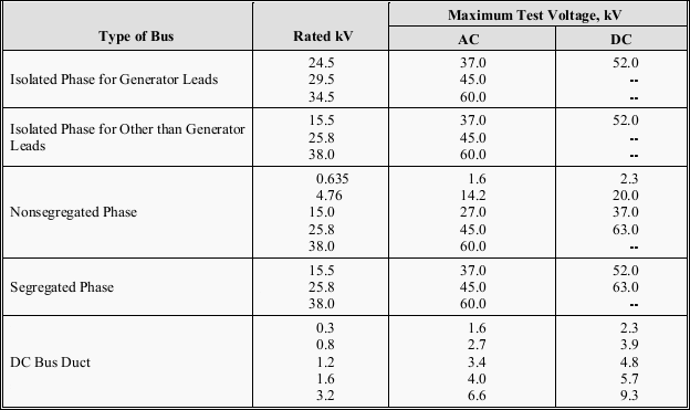
3. Perform a dielectric withstand voltage test on each busway, phase-to-ground with phases not under test grounded, in accordance with manufacturer’s published data. In the absence of manufacturer’s published data, use Table 100.17.
Where no dc test value is shown in Table 100.17, ac value shall be used. The test voltage shall be applied for one minute.
4. Perform a contact-resistance test on each connection point of uninsulated busway. On insulated busway, measure resistance of assembled busway sections and compare values with adjacent phases.
5. Perform phasing test on each busway tie section energized by separate sources. Tests must be performed from their permanent sources.
6. Verify operation of busway space heaters.
3. Test Values
3.1 Test Values – Visual and Mechanical
1. Compare bolted connection resistance values to values of similar connections. Investigate values which deviate from those of similar bolted connections by more than 50 percent of the lowest value. (7.4.1.5.1)
2. Bolt-torque levels should be in accordance withmanufacturer’s published data. In the absence of manufacturer’s published data, use Table 100.12. (7.4.1.5.2)
3. Results of the thermographic survey shall be in accordance with Section 9. (7.4.1.5.3)
3.2 Test Values – Electrical
1. Compare bolted connection resistance values to values of similar connections. Investigate values which deviate from those of similar bolted connections by more than 50 percent of the lowest value.
2. Insulation-resistance test voltages and resistance values shall be in accordance with manufacturer’s published. In the absence of manufacturer’spublished data, use Table 100.1.
Minimum resistance values are for a nominal 1000-foot busway run. Use the following formula to convert the measured resistance value to the 1000-foot nominal value:
![]()
Converted values of insulation resistance less than those in Table 100.1 or manufacturer’s minimum should be investigated. Dielectric withstand voltage tests shall not proceed until insulation-resistance levels are raised above minimum values.
3. If no evidence of distress or insulation failure is observed by the end of the total time of voltage application during the dielectric withstand test, the test specimen is considered to have passed the test.
4. Microhm or dc millivolt drop values shall not exceed the high levels of the normal range as indicated in the manufacturer’s published data.
If manufacturer’s published data is not available, investigate values which deviate from those of similar bus connections and sections by more than 50 percent of the lowest value.
5. Phasing test results shall indicate the phase relationships are in accordance with system design.
6. Heaters shall be operational.
TABLE 100.12
US Standard Fasteners – Bolt-Torque Values for Electrical Connections
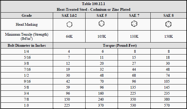


a. Consult manufacturer for equipment supplied with metric fasteners.
b. This table is based on bronze alloy bolts having a minimum tensile strength of 70,000 pounds per square inch.
c. This table is based on aluminum alloy bolts having a minimum tensile strength of 55,000 pounds per square inch.
d. This table is to be used for the following hardware types:
- Bolts, cap screws, nuts, flat washers, locknuts (18–8 alloy)
- Belleville washers (302 alloy).
TABLE 100.1
Insulation Resistance Test Values Electrical Apparatus and Systems
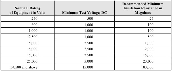
TABLE 100.17
Dielectric Withstand Test Voltages for Metal-Enclosed Bus
Resource: Acceptance Testing Specifications for Electrical Power Distribution Equipment and Systems – NETA 2003
Copyright Notice
This technical article is protected by U.S. and international copyright laws. Reproduction and distribution of PDF version of this technical article to websites such as Linkedin, Scribd, Facebook and others without written permission of the sponsor is illegal and strictly prohibited.© EEP-Electrical Engineering Portal.
Related electrical guides & articles
Premium Membership
Edvard Csanyi
Hi, I'm an electrical engineer, programmer and founder of EEP - Electrical Engineering Portal. I worked twelve years at Schneider Electric in the position of technical support for low- and medium-voltage projects and the design of busbar trunking systems.I'm highly specialized in the design of LV/MV switchgear and low-voltage, high-power busbar trunking (<6300A) in substations, commercial buildings and industry facilities. I'm also a professional in AutoCAD programming.
Profile: Edvard Csanyi





could you explain more on this test “Perform phasing test on each busway tie section energized by separate sources. Tests must be performed from their permanent sources.”
how to complete the test?
what will be the result from this test?
What is the minimum acceptable insulation resistance for aluminum busduct rated to operate at 440Volts. Please indicate the code reference standard.
Thank you.
Regards,
Romeo
What is the steps for inspection “ dielectric with stand voltage “ for busway of 1600A ?
Answer me please ..
Hi, this is a very interesting article. Congratulations!
I have a question: what is the acceptable insulation resistance of a 2500Amp copper busway 173 feet long?
This riser is made of two busways in parallel, rated 2500 amps
Thanks!
Jose
what is effect of rising of temperature within the busway at the 150% over loading continuously during 2 hr