
Estimated Study Time: 34 minutes
Transformer Nameplate (Birth Certificate)
As we all know, all substation equipment (should) have a metal plate with its “full name and address” on it. Here we’ll discuss transformer nameplate, precisely power and distribution transformers and information that their nameplates carry. A nameplate that provides important details about the transformer’s connection and operation is usually fixed to the tank in an obvious spot.
 Learn how to interpret transformer nameplate information
Since the data is frequently engraved or stamped on the nameplate, it is effectively a permanent component of the transformer. Because a transformer nameplate holds so many important details that will follow it for the duration of its service life, it has been considered to a birth certificate.
This technical article analyzes the data presented on the transformer nameplate and provides samples of real transformer nameplate information.
How to read transformer nameplate?
To read a transformer nameplate effectively, you should follow a “field-first” logic – moving from the most basic system compatibility checks (power and voltage) to the technical details required for protection and maintenance.
A typical high-voltage transformer nameplate is divided into several key zones.
- Essential Nameplate Specifications:
- Information about the Transformer Manufacturer:
- Nominal Ratings of Various Transformer Cooling Classes:
- Voltage Ratings of the Transformer (Line-to-line System & Winding Voltages):
- Nominal KVA or MVA Ratings:
- Transformer Winding Connection Diagram:
- Phase Relationships Between the Windings (Vector Diagram)
- Transformer Approximate Weight and Insulation Oil:
- Negative Pressure on the Tank
- Transformer impedance
- Basic insulation level (BIL)
- Nameplate Look
- Attachment (PDF) 🔗 Download ‘A useful guide to all practicing engineers on the subject of power system protection’
1. Essential Nameplate Specifications
A transformer’s nameplate is essentially its birth certificate and manual rolled into one. It provides the critical technical specifications required for safe installation, operation, and maintenance.
While specific requirements can vary slightly between standards like IEEE (C57.12.00) or IEC (60076-1), there is a core set of information that must be present.
1.1 Core Identification & Ratings
- Manufacturer’s Name: Who built the unit.
- Serial Number: The unique identifier for tracking factory test reports.
- Year of Manufacture: Useful for assessing the age and expected insulation life.
- Number of Phases: Usually 1-phase or 3-phase.
- Rated Frequency: Usually 50 Hz or 60 Hz.
- Rated Power (kVA/MVA): The continuous load the transformer can handle. If it has fans for cooling, it will list multiple ratings (e.g., ONAN/ONAF).
1.2 Electrical Performance
- Voltage Ratings: The nominal primary and secondary voltages (e.g., 13,200/480Y/277 V).
- Tap Voltages: A table showing the voltage ratios available at different tap positions.
- Phasor/Vector Diagram: A visual representation of the phase relationship between the high-voltage and low-voltage windings.Example: Dyn11 indicates a Delta high-voltage winding, a Wye low-voltage winding with a neutral, and a 30-degree phase shift.
- Percent Impedance (%Z): This is crucial for calculating short-circuit currents and determining how the transformer will share load when operated in parallel with another unit.
- Basic Impulse Level (BIL): The peak voltage the insulation can withstand during a lightning strike or switching surge.
1.3 Physical & Cooling Specifications
- Temperature Rise: The allowable temperature increase (usually 65∘C or 55/65∘C) over the ambient temperature.
- Insulating Liquid: The type of oil (e.g., Mineral Oil, FR3) and the total volume required.
- Total Weight: Includes the weight of the core/coils, the tank, and the oil. This is vital for rigging and foundation design.
- Connection Diagram: A schematic showing how the internal windings are connected to the external bushings.
1.4 Why All This Matters?
Missing information on a nameplate can lead to catastrophic failures. For instance, connecting two transformers in parallel without matching their impedance and vector group can cause massive circulating currents, leading to immediate tripping or fire.
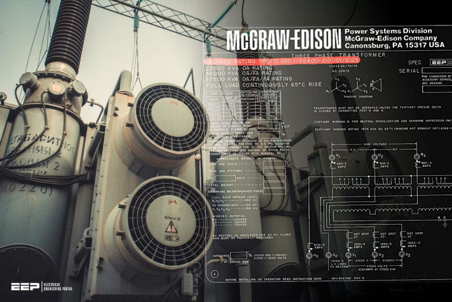
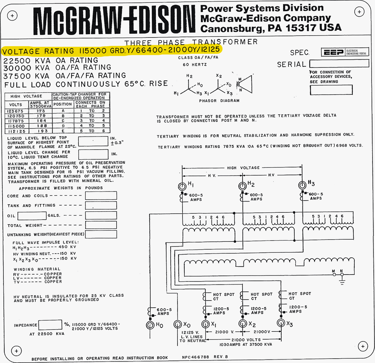
Figure 1 – Part of a transformer’s nameplate showing the voltage ratings, MVA ratings, percent impedances, connection diagram, physical layout, vector diagram, tap connections, CT connections, and BIL ratings

2. Information about the Transformer Manufacturer
The manufacturer’s section of the nameplate is more than just branding; it serves as the legal and technical “point of origin” for the equipment. In an industrial or utility setting, this information is the first thing an engineer looks for when a unit fails or needs a spare part.
Here is the breakdown of why the manufacturer’s data is critical:
2.1 The Manufacturer’s Identity
- Legal Name and Location: This includes the company name and often the city/country of the factory where the unit was assembled.
- Brand/Subsidiary: Large conglomerates (like ABB, Schneider Electric, GE, or Siemens) often acquire smaller brands.The nameplate might list both the original manufacturer (e.g., Westinghouse) and the current supporting entity to help you find the right service manual.
2.2 The Serial Number (The Most Important Label)
The serial number is the unique “DNA” of that specific transformer. If you call a manufacturer for help, they will ask for this first. It allows them to pull up the:
- Certified Test Report: The original factory results for losses, impedance, and insulation integrity.
- Internal Design Drawings: Crucial for understanding the internal bushing connections or winding geometry.
- Bill of Materials (BOM): Exactly which type of oil, gaskets, and copper were used during build.
2.3 Date of Manufacture
Usually listed by month and year (e.g., 05/2026). This is vital for:
- Warranty Tracking: Most warranties begin at the date of shipment or manufacture.
- Life Expectancy: Transformer insulation (cellulose paper) degrades over time. Knowing the age helps determine if the unit is nearing its “end of life” based on thermal aging.
- Standard Compliance: It tells you which version of the electrical codes (like IEEE or IEC) the transformer was built to meet at that time.
2.4 Why This is Vital for Maintenance?
When ordering replacement parts, like a leaking bushing or a damaged tap changer—the manufacturer and serial number are non-negotiable. Using a part from a different “model” that looks similar can lead to catastrophic dielectric failure because internal clearances are precise to the millimeter.
Further Study – A Closer Look at the Transformer Cooling Equipment
3. Nominal Ratings of Various Transformer Cooling Classes
The cooling class of a transformer determines how much heat the unit can dissipate, which directly impacts its Nominal Rating (kVA or MVA). As you add cooling equipment like fans or pumps, the transformer’s capacity increases because it can shed heat more efficiently.
On a nameplate, you will often see a “triple rating” (e.g., 12/16/20 MVA) corresponding to these stages.
3.1 Understanding the Cooling Codes (IEEE vs. IEC)
The nameplate will use a specific coding system to describe how the oil and air move.
Table 1 – Transformer cooling codes
| Code (IEEE) | Meaning | Description |
| ONAN | Oil Natural, Air Natural | The “Base Rating.” Heat rises naturally in the oil and dissipates via natural air convection on radiators. |
| ONAF | Oil Natural, Air Forced | Fans are turned on to blow air across the radiators. This typically increases capacity by 25-33%. |
| OFAF | Oil Forced, Air Forced | Pumps circulate the oil and fans blow the air. This provides the highest cooling efficiency. |
3.2 The Multiple Rating Block
The nameplate must list the power rating for every cooling stage the transformer is equipped with. This is usually presented in a hierarchy:
- Stage 1 (Base): 10,000 kVA (Self-cooled / ONAN)
- Stage 2: 13,333 kVA (First stage of fans / ONAF1)
- Stage 3: 16,667 kVA (Second stage of fans or pumps / ONAF2 or OFAF)
3.3 Temperature Rise Ratings
The nominal rating is tied strictly to the Temperature Rise, the allowable increase in temperature above a standard ambient (usually 40°C). You will see two numbers:
- 55°C Rise: The conservative rating for long-term paper insulation life.
- 65°C Rise: A higher “forced” rating using modern, thermally upgraded paper.
3.4 Auxiliary Power for Cooling
The nameplate also includes technical data for the cooling hardware itself:
- Fan/Pump Voltage: (e.g., 230V or 460V AC).
- Current Draw: Total Amps required to run the cooling system.
- Control Settings: The temperature set-points (e.g., Fans ON at 65°C oil temp).
3.5 Why This Is Critical for Operators?
If the fans fail or the “Auto” setting is accidentally turned to “Off,” the transformer cannot support its higher nominal ratings. Operating at the ONAF load while the cooling is effectively ONAN will lead to rapid insulation degradation or a catastrophic thermal trip.
Further Study – Loading issue that seriously affects transformer operation
4. Voltage Ratings of the Transformer (Line-to-line System & Winding Voltages)
Navigating the voltage section of a transformer nameplate can be a bit like learning a new dialect—the numbers look familiar, but the way they are grouped tells the real story of how the transformer unit fits into the grid.
On a high-voltage (HV) transformer nameplate, you will typically find two distinct ways of expressing voltage: the System (Line-to-Line) Voltage and the Winding Voltage.
4.1 System Voltage vs. Winding Voltage
It is crucial to distinguish between what the “grid” sees and what the individual “coils” see.
- Line-to-Line (L-L) System Voltage: This is the nominal voltage of the transmission lines connected to the transformer. When someone says “this is a 230kV substation,” they are referring to the L-L voltage.
- Winding (Phase) Voltage: This is the actual voltage across an individual internal winding.
- In a Delta (Δ) connection, Winding Voltage = System Voltage.
- In a Wye (Y) connection, Winding Voltage is the System Voltage divided by √3
Vphase = VL-L / √3
Figure 2 – An example of voltage ratings displayed in transformer nameplate

4.2 How to Read the Nameplate Designations
Manufacturers use specific shorthand to describe how the windings are built and insulated. You will likely see strings of numbers like 230,000 Grd Y / 132,790.
Common Notation Examples:
- 115,000: A straight number usually indicates a Delta connection or a line-to-line rating.
- 115,000 Y / 66,400: This indicates a Wye-connected winding where 115kV is the system L-L voltage and 66.4kV is the voltage across the actual winding.
- 230,000 Grd Y / 132,790: The “Grd” (Grounded) is vital. it means the insulation is “graded.” The insulation is thickest at the high-voltage terminal and tapers down toward the neutral point, which is intended to be solidly grounded.
4.3 Basic Insulation Level (BIL)
Right next to the voltage ratings, you’ll see a value in kV, such as BIL: 900 kV. This isn’t the operating voltage; it’s the surge withstand capability. It tells you the peak lightning or switching impulse the transformer can survive before the insulation fails.
Higher system voltages require significantly higher BIL ratings.
4.4 Tap Changer Ranges
The nameplate will also list a table of voltages for different “Taps.” High-voltage transformers usually have an On-Load Tap Changer (OLTC) or a De-Energized Tap Changer (DETC) to account for fluctuations in the grid.
- Nominal Tap: The center position (e.g., Position 3 or 5).
- Range: Usually ±10% in steps of 0.625% or 1.25%.
- Example: A 138kV transformer might have taps ranging from 124.2kV up to 151.8kV to maintain a steady secondary voltage even if the transmission supply is “weak.”
Table 2 – Transformer tap changer ranges
| Tap Position | Voltage (L-L) | Rated Current |
| 1 (Raise) | 144,900 V | 400 A |
| 3 (Nominal) | 138,000 V | 420 A |
| 5 (Lower) | 131,100 V | 442 A |
Video Lesson – TTR test using testing kit
5. Nominal KVA or MVA ratings
Transformer MVA rating is never a static number—it is a thermal limit. Because heat is the primary enemy of transformer insulation (cellulose paper and oil), the nameplate serves as a guide for how much power you can push through the unit before that insulation begins to degrade at an accelerated rate.
Here is how those MVA ratings, temperature rises, and cooling modes interact on a standard nameplate.
5.1 The Triple MVA Rating
Most substation transformers are designed with “stages” of cooling. As you add fans or pumps, the transformer’s ability to dissipate heat increases, allowing for a higher nominal MVA rating.
- Base Rating (ONAN): This is the “Natural” rating. No fans are running. The transformer might be rated at, say, 30 MVA.
- First Stage (ONAF1): Fans turn on. The rating jumps to 40 MVA.
- Second Stage (ONAF2/OFAF): More fans or oil pumps kick in. The rating reaches its maximum, perhaps 50 MVA.
If you see a nameplate marked 30/40/50 MVA, it means the transformer is physically the same size, but its capacity is “unlocked” by the cooling system.
Related Guide – Technical specification for construction of 33/11 kV 2×31.5 MVA substations
Technical specification for construction of 33/11 kV 2×31.5 MVA power substations
5.2 Winding Temperature Rise (ΔT)
The “Nominal Rating” is always tied to a specific temperature rise above the ambient temperature (usually assumed to be 30°C or 40°C).
Common Nameplate Values:
- 55°C Rise: An older standard. If the ambient is 30°C, the average winding temperature should not exceed 85°C.
- 65°C Rise: The modern standard using thermally upgraded paper. This allows the windings to run hotter (up to 95°C average) without losing structural integrity.
- 55/65°C Dual Rating: You will often see both. This means the transformer can provide a certain MVA at a 55°C rise, but if you are willing to let it run hotter (65°C rise), you can squeeze out roughly 12% more capacity.
5.3 The “Hot Spot” Constraint
While the nameplate gives you an average winding rise, the real danger is the Hot Spot. This is the single hottest point inside the windings, usually near the top of the tank where the oil is hottest.
For a 65°C rise transformer, the hot spot is generally designed not to exceed 110°C at its maximum rated MVA and standard ambient conditions. If the hot spot exceeds 110°C, the chemical bonds in the paper insulation start to break down rapidly.
Recommended – A practical handbook for electrical engineers (beginners)
6. Transformer Winding Connection Diagram
At the High Voltage level, the transformer nameplate provides more than just a basic wiring diagram; it serves as a technical blueprint for grid synchronization and protection settings. Because 220kV systems are almost always solidly grounded, the diagram will specifically highlight the insulation levels and the “Graded” nature of the windings.
6.1 Vector Group for HV Transformers
In high-voltage transmission, the most common connection is YNd11 or YNyn0+d (220kV example).
- YN (High Voltage side): Wye (Star) connection with the Neutral brought out (N) for grounding. At 220kV, this neutral is usually “Graded,” meaning the insulation is thinner near the neutral point than at the line terminals.
- d (Low/Tertiary Voltage side): Delta connection. Even if the transformer is Wye-Wye, it often has a “buried” Delta tertiary winding to trap third-harmonic currents and provide a path for zero-sequence current during faults.
- 11 or 0: Indicates the phase shift. 11 means the LV leads the HV by 30°.
Further Study – Contract drawings for a power transformer
Contract drawings for a power transformer – The checklist you should always follow
6.2 The Winding Schematic
The nameplate will feature a line drawing of the coils. For a 220kV unit, look for these specific details:
- Taps (OLTC): The diagram will show which winding (usually the HV or a separate regulating winding) contains the On-Load Tap Changer. It will specify the physical position of the taps (e.g., 17 or 19 positions).
- Bushing Current Transformers (BCTs): High-voltage nameplates often include small circles around the bushing leads in the diagram. These represent the internal CTs used for differential and overcurrent protection.
- Tertiary Winding: Labeled as 3U, 3V, 3W or Y1, Y2, Y3. This winding might be used for station service power or purely for harmonic stabilization.
Figure 3 – Transformer nameplate with clear identification of a winding schematic
6.3 Voltage and Insulation Levels (BIL)
On a 220kV nameplate, the connection diagram is usually adjacent to a table of Basic Insulation Levels (BIL).
Table 3 – Voltage and Insulation Levels for a 220kV transformer
| Terminal | Nominal Voltage | Connection | BIL (Lightning Impulse) |
| HV (1U, 1V, 1W) | 220 kV | Wye (Grounded) | 900 kV or 1050 kV |
| LV (2u, 2v, 2w) | 110 kV or 66 kV | Wye or Delta | 450 kV or 550 kV |
| Neutral (1N) | 0 kV | Solidly Earthed | 95 kV (Reduced Insulation) |
6.4 Interpretation of Phase Displacement
For 220kV substations, the phase displacement is critical for Differential Protection (87T).
If the diagram shows YNd11, the protection relay must be programmed to compensate for a -30° shift so that the current entering the HV side and leaving the LV side is compared correctly.
The diagram will also specify the Phasing sequence (usually A-B-C or U-V-W clockwise).
6.5 Terminal Marking Standards
At this voltage class, you will typically see IEC 60076 or IEEE C57.12.00 markings:
- HV Side: 1U, 1V, 1W (IEC) or H1, H2, H3 (IEEE).
- LV Side: 2u, 2v, 2w (IEC) or X1, X2, X3 (IEEE).
- Neutral: 1N or H0.
Safety Warning: On 220kV nameplates, check if the Neutral is “Solidly Grounded” or “Floating.” Attempting to operate a graded-insulation neutral without a proper ground can lead to catastrophic insulation failure.
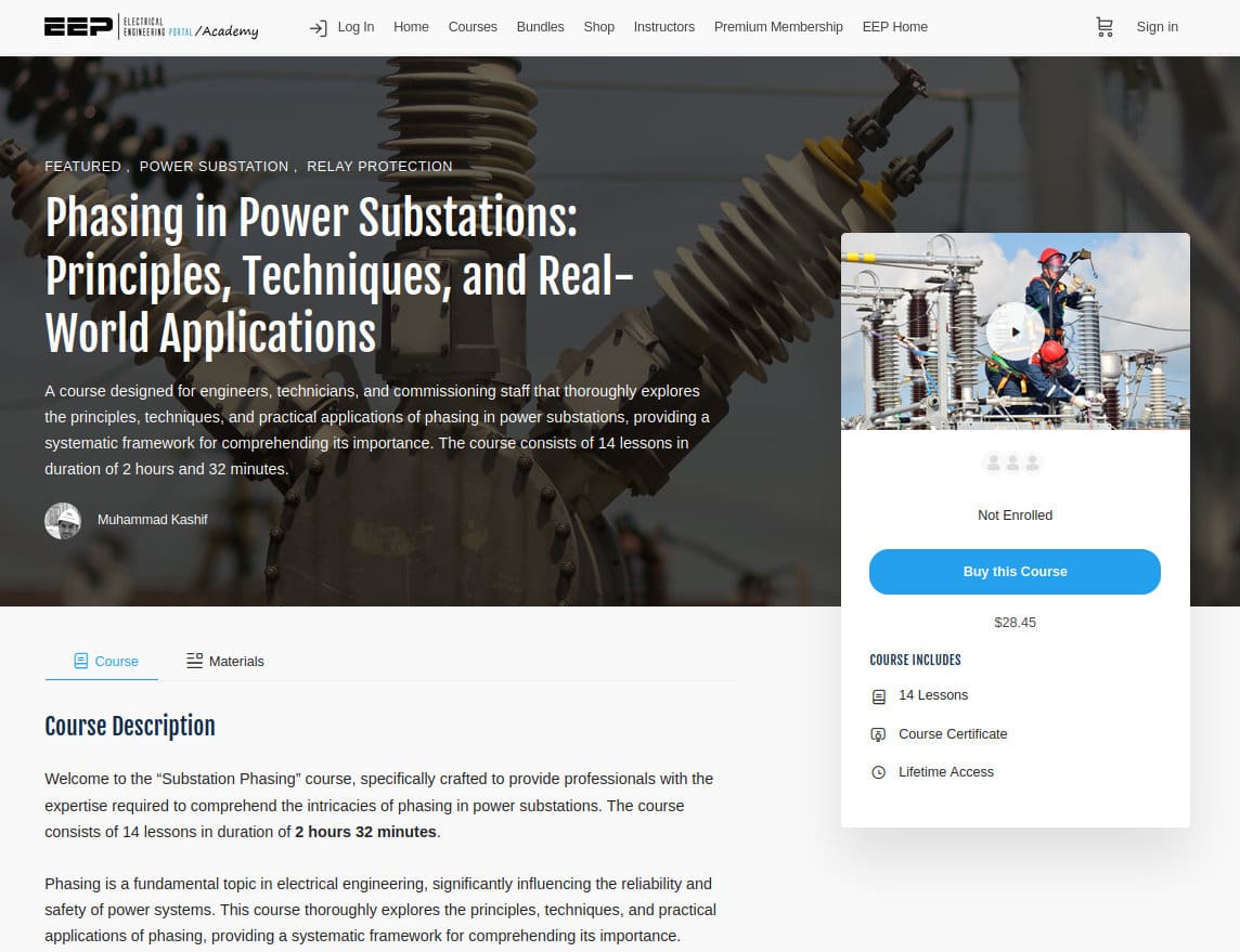
Good Course – Phasing in Power Substations: Principles, Techniques, and Real-World Applications
7. Phase Relationships Between the Windings (Vector Diagram)
Transformer windings’ three phases can be connected in a zigzag, delta, or star configuration. The transformer’s nameplate depicts the vector group (star: Y or y; delta: D or d; zigzag: Z or z), with small letters for the windings on the other voltage levels and a capital letter for the side with the highest voltage.
The letters N and n stand for the neutral connection if it is removed from the transformer tank. The corresponding vector group number represents the phase-shift as multiples of 30° of the phase angle of the lower voltage side’s line-to-earth voltages in relation to the corresponding higher voltage side’s line-to-earth voltages (in a mathematically positive sense).
Common vector groups for two-winding transformers are presented in Figure 4.
Figure 4 – Vector group and circuit arrangement of three-phase transformers
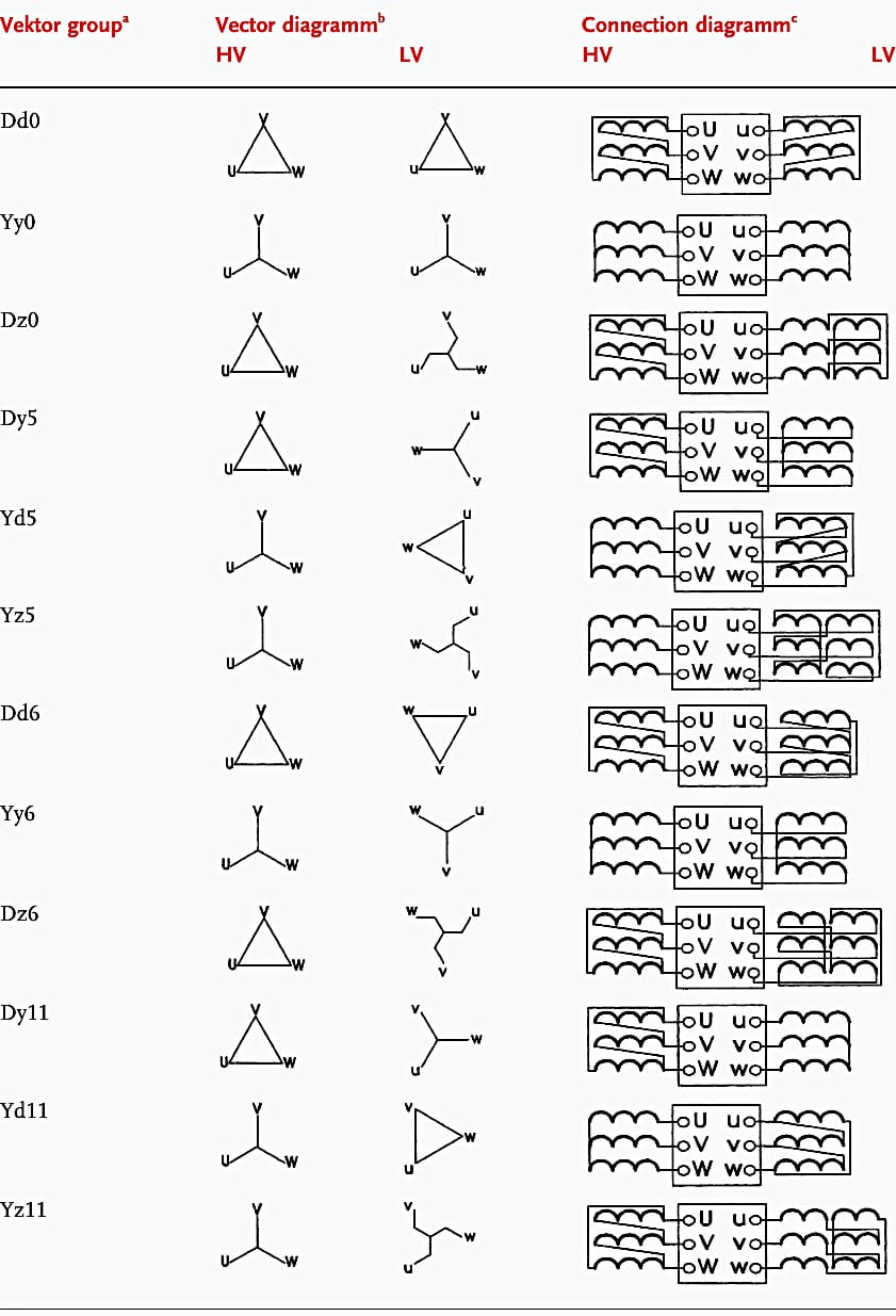
Where:
- a – In case the neutral is brought out of the tank, also include N and/or n.
- b – 1U, 1V, 1W for the highest voltage; 2U, 2V, 2W and/or 3U, 3V, 3W for lower voltage connections.
- c – Same direction of coil winding direction starting from connection point.
The impedance of the zero-sequence component and the permissible loading of the transformer neutral are significantly impacted by the winding arrangement, whether it be in a star, delta, or zigzag connection. If the neutral is grounded, windings coupled in a star or zigzag pattern have a definite zero-sequence impedance.
The zero-sequence impedance of delta-connected windings with ungrounded star or zigzag connections is infinite.
The ability to carry the rated current of the earthed winding through the neutral, represented as the ratio of the current through earth IE to the transformer rated current IrT, is known as the maximum permissible loading of the transformer neutral.
When the power system is operated with resonance earthing via a Petersen coil or low-impedance earthing, a high maximum allowable loading of the neutral is required.
The specifics of a transformer’s construction determine its X0/X1 ratio. The ratio is X0/X1 = 3–10 for vector group Yy, Yz transformers with a three-leg core; it is X0/X1 = 10–100 for three single-phase transformers or transformers with a five-leg core. The zero-sequence impedance to positive-sequence impedance ratio of low-voltage transformers is typically X0/X1 = 1.
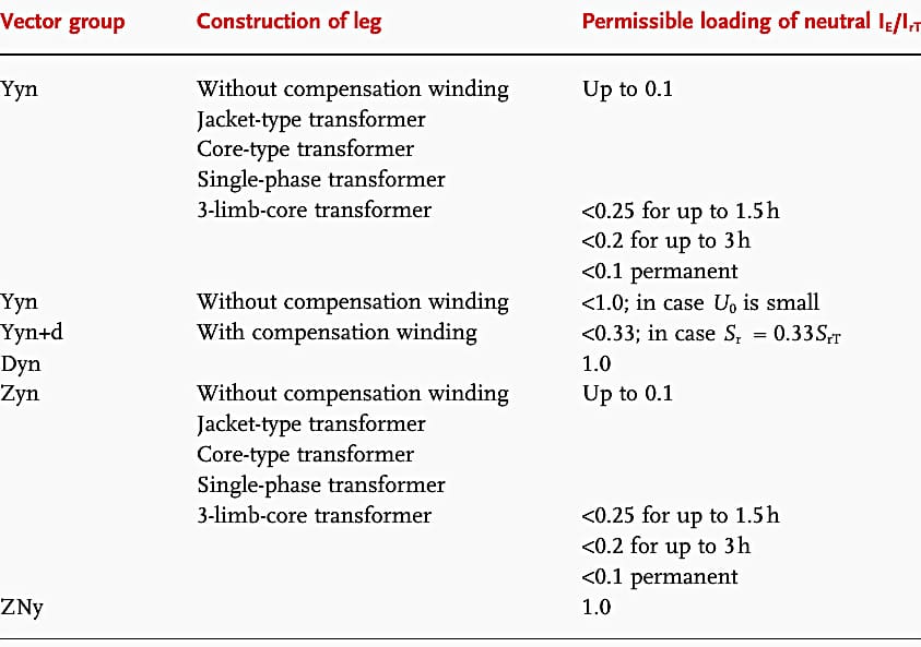
The maximum permissible loading of transformer neutrals for various vector groups and construction types is summarized in Figure 5.
Figure 5 – Maximal permissible loading of transformer neutrals (N or n means that in this case the winding is actually grounded)
Learn more about transformer vector groups by following these two articles:
Further Study – Understanding Vector Group of Transformer
8. Transformer Approximate Weight and Insulation Oil
On an HV nameplate, weights and oil volumes are typically grouped toward the bottom or in a dedicated “Weights and Measures” section.
8.1 Standard Weight Breakdowns
Because HV transformers are often shipped in pieces, the nameplate breaks the weight down so engineers know what crane capacity is needed at each stage:
- Core and Coils: The weight of the internal “active part.”
- Tank and Fittings: The weight of the steel enclosure, radiators, and bushings.
- Untanking Weight: The maximum weight to lift when pulling the core out of the tank for repairs.
- Total Weight: The “In-Service” weight (Core + Tank + Oil).
- Transport Weight: The weight of the unit as it arrives on the trailer (usually without oil and radiators).
8.2 Insulation Oil Data
The nameplate will specify:
- Total Oil Volume: Listed in Liters or Gallons.
- Weight of Oil: Necessary for calculating the total mass.
- Type of Oil: Usually “Mineral Oil” or a specific brand/standard (e.g., ASTM D3487).
8.3 Approximate Reference Values
While every unit is custom-built, here are typical “nameplate” figures for common HV substation sizes:
Table 4 – Approximate reference values of power transformers
| Transformer Rating | Primary Voltage | Total Oil (Liters) | Total Weight (Tons) |
| 10 MVA | 66 kV | ~6,500 L | ~22 Tons |
| 40 MVA | 110 kV | ~18,000 L | ~65 Tons |
| 100 MVA | 220 kV | ~35,000 L | ~130 Tons |
| 250 MVA | 400 kV | ~75,000 L | ~280 Tons |
The nameplate volume refers to the oil at a specific reference temperature (usually 20°C). It’s important to note that high-voltage transformers have a Conservator Tank on top. As the transformer heats up under load, the oil expands.
The nameplate volume includes the oil required to fill the main tank and the minimum level of the conservator.
Good Reading – The art of predicting the fate of a power transformer by looking into a cup of oil
The art of predicting the fate of a power transformer by looking into a cup of oil
9. Negative Pressure on the Tank
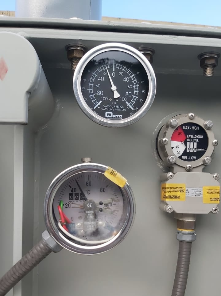
Contemporary power transformers are engineered to be “vacuum oil filled“. Prior to initiating the vacuum process on a transformer, it is essential to examine the nameplate to confirm that the tank is engineered to endure negative pressures. The nameplate also specifies the acceptable range of operating pressures.
The standard atmospheric pressure is 15 psi at sea level. Consequently, when the transformer is in a perfect vacuum, the negative pressure within the tank will be roughly 15 psi at sea level, and marginally lower at higher altitudes.
Figure 6 – Transformer pressure vacuum gauge
10. Transformer Impedance
Transformers with high impedance voltage reduce the short-circuit level, but the reactive power losses are increased and the tap-changer need to be designed for higher voltage drops.
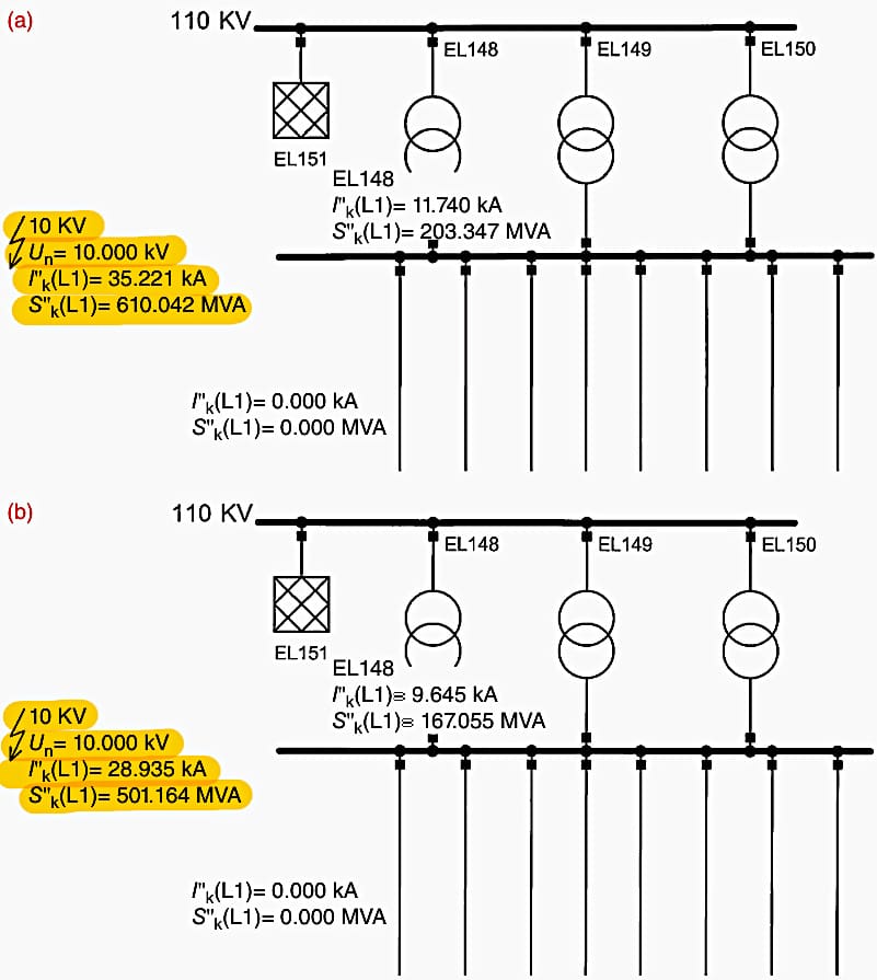
Figure 7 shows the equivalent circuit diagram of a 10 kV system fed from a 110 kV system by three transformers, SrT = 40 MVA. The system load is SL = 72 MVA, cos ϕ = 0.8. The short-circuit power of the 110 kV system is SkQ′′ = 2.2 GVA; the voltage at the 10 kV busbar is to be controlled within a bandwidth of ±0.125 kV around U = 10.6 kV.
Figure 7 – Equivalent circuit diagram of a 10 kV system with incoming feeder. Results of three-phase short-circuit current calculation. (a) Impedance voltage 13%; (b) impedance voltage 17.5%.
The relevant results of load-flow and short-circuit analysis are outlined in Figure 8.
Figure 8 – Result of load-flow and short-circuit analysis according to Figure 7
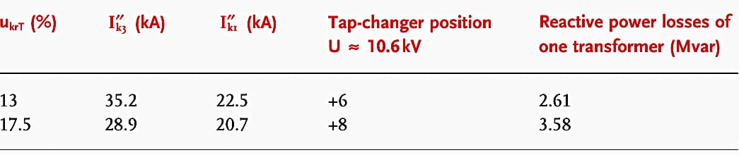
As can be seen, the increase of the impedance voltage from 13% to 17.5% reduces the short-circuit current but increases the reactive power losses and increases the number of steps at the tap-changer to control the voltage.
Watch Video – Percentage Impedance of Transformer
11. Basic insulation level (BIL)
The nameplate indicates the basic insulation levels (BILs) for the windings at each terminal and the BIL for the bushings. These are presented as full-wave test values expressed in kV.
Figure 9 – Part of a transformer’s nameplate showing the basic insulation levels (BILs) of the windings at each of the terminals and the BIL of the bushings

Further Study – What Is The Basic Insulation Level (BIL)
12. Transformer Nameplate Look
There is some flexibility in the rules regarding the layout and the look of the transformer nameplate, which allows for some degree of creativity. Every single manufacturer organizes the data in a somewhat different fashion.
Depending on the requirements of the customer, there are some customers who demand a particular layout.
Figure 10 – Transformer nameplate

13. A useful guide to all practicing engineers on the subject of power system protection
Download: A useful guide to all practicing engineers on the subject of power system protection (for premium members only):
Related electrical guides & articles


Edvard Csanyi
Hi, I'm an electrical engineer, programmer and founder of EEP - Electrical Engineering Portal. I worked twelve years at Schneider Electric in the position of technical support for low- and medium-voltage projects and the design of busbar trunking systems.I'm highly specialized in the design of LV/MV switchgear and low-voltage, high-power busbar trunking (<6300A) in substations, commercial buildings and industry facilities. I'm also a professional in AutoCAD programming.
Profile: Edvard Csanyi

What does this sentence mean: “If the nameplate designates a winding voltage is designated with a Y but without a slash, the winding is permanently Y-connected without bringing out a neutral connection.”?
How to convert 5 winding transformer impidence to any 3 winding transformer or any 2 winding transformer impidence’s, is there any formula to convert, please send me.
Thanking you.
Like to get educative information from EEP
These was a wonderful article.am impressed
Dear Er. Edvard Csanyi,
Greetings for the time of the day(IST=+5.30 hrs).
Sir, I appreciate this Article very much. Many field Engineers/asset managers are ignorant about what is written on the R&D plate of a transformer.I have recently written an Article titled as” KYT( Know Your Transformer)”this is about the same theme as your Article but contains about EHV transformers in a Grid network.If you feel like viewing the same, I shallshare the same with you, Sir.With kind regards.K.K.Murty,(India)
Very impressive and educative especially for us in electricity Distribution Industry.