
Transformer nameplate (‘name’ on the plate)
As we all know, all substation equipment (should) have a metal plate with its “name” on it. Here we’ll discuss transformer nameplate, precisely power and distribution transformers and information that their nameplates carry. It’s usually attached to the tank in a visible place and gives vital information on how the transformer is connected and operated. The data is printed or stamped on the nameplate more often, so it is essentially a permanent part of the transformer.
 Learn how to interpret transformer nameplate information
A transformer nameplate has been compared to a birth certificate because it contains so many vital statistics that will follow it throughout its service life.
In this technical article, examples of actual transformer nameplate information are illustrated and the data provided on the nameplate are analyzed.
How to read transformer nameplate
- Minimum nameplate requirements
- Manufacturer’s information
- Cooling class, number of phases, and operating frequency
- Transformer voltage ratings
- KVA or MVA ratings
- Winding connection diagram
- Transformer-phasor or vector diagram
- Weights and oil capacity
- Operating pressure range
- Transformer impedance
- Basic insulation level (BIL)
- Nameplate layout
1. Minimum transformer nameplate requirements
There are hundreds of thousands of transformer nameplates installed out there with differences in size and information displayed. However, the minimum information to be shown on a transformer nameplate depends on the transformer’s KVA rating as specified in the standards.
The standards require the following information for transformers rated above 500 KVA:
- Name of manufacturer
- Serial number
- Month/year of manufacture
- Cooling classWhere the class of transformer involves more than one rating, all ratings are shown. Windings having different ratings have their individual KVA ratings described. If the transformer has more than one temperature rating, these ratings are shown on the nameplate. Provisions for future cooling equipment are indicated.
- Number of phases
- Frequency
- KVA or MVA rating
- Voltage ratings. The voltage ratings of a transformer or autotransformer windings are separated by a dash (-).
- Tap voltages. The tap voltages of an individual winding are separated by a slash (/).
- Rated temperature rise, °C
- Polarity (single-phase transformers)
- Phasor or vector diagram (polyphase transformers)
- Percent impedance. The percent impedance is specified between each pair of windings with the voltage connection and the KVA base stated. The percent impedance shall be tested.
- Basic lightning impulse insulation levels (BIL). The BIL of each winding and each bushing are specified.
- Approximate mass of the core and coils, tank and fittings, insulating oil, total weight, and heaviest piece.
- Connection diagramThe connection diagram shows all winding terminations with a schematic plan view showing all fixed accessories. The schematic plan view generally shows the low-voltage side of the transformer at the bottom . The location and polarity shall be shown for all current transformers used for metering, relaying, or drop compensation.
- Installation and operating instructions references
- The word ‘‘transformer’’ or ‘‘autotransformer’’
- Suitability for step-up operation. Since the MVA rating is generally specified at the output winding at the nominal output winding voltage, the MVA rating for step-up operation will generally be different than the MVA rating for step-down operation, unless specified.
- Maximum positive and negative operating pressures of the oil preservation system, kPa or psi
- Maximum negative pressure of the tank for vacuum filling
- Liquid level below the top surface of the highest point of the highest manhole flange at 25°C
- Change in liquid level per 10°C change in liquid level
- Oil volume of each transformer compartment
- Type of insulating liquid. The nameplate shall also have the following note: ‘‘Contains no detectable level of PCB (less than 2 PPM) at the time of manufacture.’’
- Conductor material of each winding

connections, CT connections, and BIL ratings
2. Manufacturer’s information
The manufacturer’s name usually appears prominently at the top of the nameplate. Just below the manufacturer’s name is a unique serial number or shop order number to identify the particular unit so its manufacturing and design records can be traced.
In some respects, the nameplate is equivalent to a birth certificate.
3. Cooling class, number of phases, and operating frequency
The transformer cooling class, number of phases, and the operating frequency are usually specified near serial number. There are a variety of cooling classes. The more common types are reviewed in Table 1.
Table 1 – Designations and descriptions of the cooling classes used in power transformers
| NEMA designation | IEC designation | Description |
| OA | ONAN | Oil-air cooled (self-cooled) |
| FA | ONAF | Forced-air cooled |
| OA/FA/FA | ONAN/ONAF/ ONAF | Oil-air cooled (self-cooled), followed by two stages of forced-air cooling (fans) |
| OA/FA/FOA | ONAN/ONAF/ OFAF | Oil-air cooled (self-cooled), followed by one stage of forced-air cooling (fans), followed by 1 stage of forced oil (oil pumps) |
| OA/FOA | ONAN/ODAF | Oil-air cooled (self-cooled), followed by one stage of directed oil flow pumps (with fans) |
| OA/FOA/FOA | ONAN/ODAF/ ODAF | Oil-air cooled (self-cooled), followed by two stages of directed oil flow pumps (with fans) |
| FOA | OFAF | Forced oil/air cooled (with fans) rating only – no self-cooled rating |
| FOW | OFWF | Forced oil/water cooled rating only (oil/water heat exchanger with oil and water pumps) – no self-cooled rating |
| FOA | ODAF | Forced oil/air cooled rating only with directed oil flow pumps and fans – no self-cooled rating |
| FOW | ODWF | Forced oil/water cooled rating only (oil/water heat exchanger with directed oil flow pumps and water pumps) – no self-cooled rating |
Let’s say a wor about the transformer coolants and their applications.
In certain applications, the selection of oil or air is determined by safety factors, including the risk of fire. Air-cooling is prevalent for units within buildings due to the less fire risk. Although transformer oil is flammable, the risk of fire is typically minimal due to the transformer tank being sealed from external air or the oil surface being covered with an inert gas like nitrogen.
Despite the higher flash point of oils, severe heating or sparking within an oil-filled tank may result in the discharge of flammable gases.
Other cooling mediums, such as pressurized sulfur hexafluoride gas, have restricted applications. This gas is highly inert and possesses a greater breakdown strength than air, making it suitable for high-voltage applications where oil is impractical and air fails to deliver sufficient dielectric strength. Typically, standard transformer oil is utilized in oil-cooled transformers. Nonetheless, various kind of oil are employed for specialized applications.
For instance, silicone oil. It can operate at higher temperatures compared to ordinary transformer oil while presenting a less fire threat.
Further Study – Why cooling is essential for long transformer life?
4. Voltage ratings
The voltage rating of the transformer is specified in terms of both the lineto-line system voltages and the winding voltages. For example, a 230 kV Grd.Y to 69 kV Grd.Y transformer with a 12.47 kV tertiary would have the following voltage rating on its nameplate:
230000GR.Y / 132800-69000 GR.Y / 39840-12470
The hyphens separate the voltage ratings of one winding from the voltage ratings of the other windings. In this illustration, 230000 GR.Y / 132800 is the rating of the high-voltage winding, 69000 GR.Y / 39840 is the rating of the low-voltage winding, and 12470 is the rating of the tertiary winding. The voltage ratings are always given in volts.
The example 230000 GR.Y / 132800-69000 GR.Y / 39840-12470 designates the 12,470 V tertiary winding by a single number without a slash appearing because the winding ratings and the line-to-line voltage of the system are the same. In other words, the windings are connected phase-to-phase in a ∆.
If the nameplate designates a winding voltage is designated with a Y but without a slash, the winding is permanently Y-connected without bringing out a neutral connection. For example, 66000-12470Y shown on the nameplate indicates a ∆-connected primary winding rated 66,000 V with a Y-connected secondary winding suitable for connection to a 12,470 V system.

Example of nameplate voltage ratings
Two transformers have the following nameplate voltage ratings:
- Transformer 1: 69000-12470 GR.Y / 7200
- Transformer 2: 69000 GR.Y / 39840-12470
Explain the difference between the two transformers. What are the TTRs of these transformers? Can the two transformers be operated in parallel?
Transformer 1 – It has a ∆-connected primary with a line-to-line rating and a winding rating of 69,000 V. The secondary is grounded-Y connected with a line-to-line rating of 12,470 V and a winding rating of 7200 V. The TTR of this transformer equals the ratio of the winding ratings: 69,000/7200 = 9.583.
Transformer 2 – It has a grounded-Y connected primary with a line-to-line rating of 69,000 V and a winding rating of 39,840 V. The secondary is ∆-connected with a line-to-line rating and a winding rating of 12,470 V. The TTR of this transformer equals the ratio of the winding ratings: 39,840/12,470 = 3.195.
If both transformers have the same phase angle displacement, which is 30° for a standard design, and the percent impedance values are nearly the same, these transformers may be operated in parallel.
Video Lesson – TTR test using testing kit
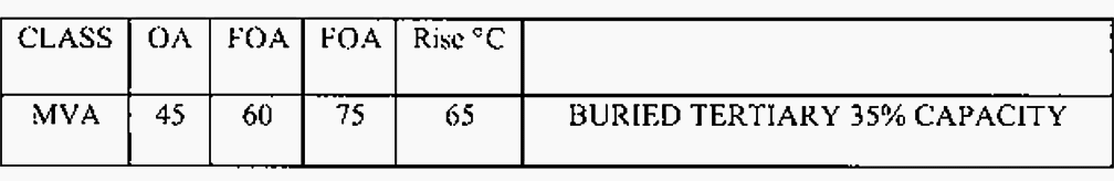
5. KVA or MVA ratings
The nominal KVA or MVA ratings are shown on the nameplate for a specified winding temperature rise and cooling mode. For example, consider an OA/FOA/FOA cooling class transformer with ‘‘45/60/75 MVA Continuous at 65°C Temperature Rise’’ specified on its nameplate.
This transformer is designed to operate continuously at 45 MVA as a self-cooled (OA) transformer, or at 60 MVA with one stage of forced oil and forced air cooling, or at 75 MVA with two stages of forced oil and forced air cooling with an average winding conductor temperature at 65°C above the ambient air temperature.
Some oil-filled transformers have KVA and MVA ratings specified at both 65°C rise and 55°C rise. This is because transformers built prior to the 1960s were limited to an average winding temperature rise of 55°C because of the types of insulating materials that were available at that time. Standard ratings developed for these transformers were based on the 55°C temperature rise.
Later, improved insulating materials became available, which allowed transformers to operate at a 65°C temperature rise. The KVA ratings at 65°C rise were higher than the ‘‘standard’’ ratings that were previously developed.
Certain high-performance insulating materials such as Nomex and silicone fluids allow operation at 75°C rise or even higher temperatures. The nameplate ratings would reflect the KVA ratings at the higher temperature rise.
For two-winding transformers, there is usually only one set of KVA or MVA values shown, because it is understood that the primary and secondary windings must have the same KVA capabilities. This is not true for three-winding transformers, however, since the tertiary is often not designed to the same KVA capabilities as the primary and secondary windings.
The nameplate for a three-winding transformer could read as shown in Figure 3 above. Sometimes, the details of the tertiary ratings are given in the winding connection tables and diagrams, discussed below.
Recommended – A practical handbook for electrical engineers (beginners)
6. Winding connection diagram
The actual winding connections are shown in a diagram with each winding and its taps labeled. A set of tables then specifies the voltage ratings, ampere ratings, and the connections for all the available taps. For transformers with load tap changing equipment, the connection diagrams and the accompanying tables are quite extensive.
The connection diagram usually also gives the general physical layout of the transformer, showing the placement of the bushings and the locations of current transformers (CTs) and a schematic representation of the load tap changing equipment, including the preventative autotransformer, moving contacts, arcing contacts, transfer switch, and reversing switch.
A portion of an actual nameplate that shows the winding connection diagram is illustrated in Figure 4. The nameplate depicted is rather interesting. The transformer has a load tap changer. From the connection diagram we see that the buried tertiary is also a tapped winding that supplies a buck/boost voltage to the secondary windings through auxiliary transformers connected between the tertiary and the secondary.
Therefore, the tertiary simultaneously provides four important functions:
- It provides a path for third harmonic currents.
- It helps stabilize voltages in the Y-Y primary-secondary connection.
- It provides a grounding bank action by providing a path for zero-sequence currents.
- It provides the necessary voltage taps for regulating the low-side voltage.
The voltage taps for the primary and secondary are shown on the connection diagram and on the winding rating tables in Figure 4. These also specify which terminal numbers and letters are connected for each tap. This transformer has a total of 14 current transformers that are used for metering, protective relaying, and other purposes. Note the CTs marked ‘‘LDC’’ and ‘‘WDG.TEMP’’.

connections, CT connections, and BIL ratings
The term LDC stands for line drop compensation. The LDC CT supplies metered line current to a compensating device in the voltage regulator controls. The compensating device effectively moves the voltage control point into the system connected to the secondary winding.
The CT labeled WDG.TEMP supplies current to the winding temperature gauges. As previously discussed, these gauges use a heating element surrounding a temperature probe mounted in the top oil in order to mimic the winding temperature. The ratios of these CTs would be shown on an actual nameplate, but this information is not shown in Figure 4.
Note the terminals labeled P1, P2, and P3. These terminals correspond to the connections to the preventative autotransformer. The two series arcing contacts per phase that are in series with the movable contacts are shown as well.
7. Phasor or vector diagram
All nameplates for polyphase transformers include vector diagrams to show the phase relationships between the windings. If the transformer has a nonstandard phase shift, this will be indicated on the vector diagram. Some transformers have terminal boards that can be wired to provide different configurations such as either ∆-Y or Y-Y, or unusual phase displacements, such as Y-Y with a 180° phase displacement between the primary and secondary.
Each of the possible configurations is shown on the vector diagram.
The vector diagram on the nameplate shown in Figure 5 shows the standard phase angle displacement of 0° for a Y-Y connected transformer.

The system designers primarily determine the necessary vector grouping pattern for each voltage level in the network, however numerous factors influence this selection. Critical elements from the user’s perspective include:
- The capacity to operate in parallel and the vector displacement between the systems connected to each transformer winding
- Establishment of a neutral earth point or points, where the neutral is connected to earth either directly or via an impedance.
- The feasibility of transformer design and the expenses related to insulation specifications.
- The Z winding mitigates voltage unbalance in systems with uneven load distribution across phases and allows for neutral current loading with intrinsically low zero-sequence impedance. Consequently, it is frequently employed for grounding transformers.
Further Study – Understanding Vector Group of Transformer
8. Weights and oil capacity
To avoid mechanically overloading equipment when handling and rigging large transformers, weight is an important consideration. Also, if insulating oil is to be removed for shipping, it is important to know quantities of oil that are involved. The nameplate provides a convenient reference for these data, which is permanently attached to the transformer.
The nameplate has a table of approximate weights (that are usually somewhat conservative) and the oil capacity, usually given in U.S. gallons. The weights and oil volumes are broken down by components and oil compartments. The untanking weight is the weight of the heaviest piece that must be lifted for disassembly.
There is also information showing the internal oil level at 25°C that is used to properly fill the transformer, plus an indication of the change in oil level per change in temperature. Figure 6 shows the manner in which this information is typically shown on actual nameplates.
Example #1
A transformer is to be loaded onto a rail car after the oil is drained from the main tank and the LTC compartment. A 150 T crane is available. Using the information in Figure 6 above, is the crane’s capacity adequate?
The untanking weight of the unit (core and coils) is 118,000 lb and the weight of the tank and fittings is 88,000 lb. Thus, the net weight of the transformer without oil is 118,000 lb + 88,000 lb = 206,000 lb = 103 T. The capacity of the crane is adequate to lift the transformer without oil. Note that when the transformer is filled with oil, the total weight is 306,200 lb = 153.1 T, which exceeds the capacity of the crane.
Example #2
The oil level of a particular transformer is shown in Figure 6. The transformer is being filled with oil at a substation at an ambient temperature of 30°C (86°F). Where should the oil level be after when the filling is complete?
According to Figure 6, the oil level at 25°C is 12.6 in. below the top of the manhole. The change in oil level is 1.17 in. per 10°C change in oil temperature. Since the ambient temperature is 5°C the reference temperature, the change in oil level is one-half of 1.17 in., or 0.585 in. above the reference point of 12.6 in.
Therefore, the proper oil level is 12.6 in − 0.585 in. = 12.015 in. below the top of the manhole.
Further Study – The art of predicting the fate of a power transformer by looking into a cup of oil
The art of predicting the fate of a power transformer by looking into a cup of oil
9. Operating pressure range
Most modern power transformers are designed to be ‘‘vacuum oil filled’’. Before attempting to ‘‘pull vacuum’’ on a transformer, it is important to consult the nameplate first to verify that the tank is designed to withstand the negative pressures. The positive range of operating pressures is also specified on the nameplate.
The nominal atmospheric pressure is 14.7 psi at sea level. Thus, when the transformer contains a perfect vacuum, the negative pressure on the tank will be approximately 15 psi at sea level, and slightly less at higher elevations.
In the example shown in Figure 7, we see that this transformer is designed to be vacuum oil filled under a ‘‘perfect vacuum’’ equal to about 15 psi of negative pressure.

10. Impedance
The transformer impedance, sometimes referred to as ‘‘impedance volts’’ on the nameplate, is specified for each of pair of windings as a percent value on a specific KVA base. For two-winding transformers, only one value of impedance is given, corresponding to the high-to-low voltage series impedance at a KVA base that usually corresponds to the KVA rating of the primary and secondary windings.
- For a transformer having multiple cooling classes, the KVA base is usually specified as the OA rating of the transformer.
- For a transformer having three or more windings, the situation is complicated by the fact that not all of the windings have the same KVA rating.
Therefore, the KVA base used to for the percent impedance of each pair of windings must be specified on the nameplate
When doing analysis using the nameplate impedance values, care must be exercised to convert the percent impedances to a common KVA base. Since the nameplate is normally fabricated before transformer assembly is completed, some of design data is etched on the nameplate. The last two items to be determined are the transformer serial number and the percent impedance values that must be determined by test.
Therefore, the percent impedances are usually stamped on the nameplate just before the transformer is shipped from the factory.
Example
Convert the percent impedance values shown in Figure 7.4 into per unit impedances on a common 100 MVA base.
- Primary to secondary: 0.16 × 100 MVA/75 MVA = 0.213 per unit
- Primary to tertiary: 0.14 × 100 MVA/26.26 MVA = 0.533 per unit
- Secondary to tertiary: 0.12 × 100 MVA/26.26 MVA = 0.457 per unit
The primary parameter for a transformer is the short-circuit (internal) impedance. The lowest number is constrained by the least physical distance between windings, whilst the maximum is restricted by the impact of the corresponding high leakage flux. This indicates that extreme values are constrained by the design element.
Three-phase systems also account for zero sequence impedance, as it influences the size of fault currents that flow between the neutral of a star-connected winding and the ground during phase-to-earth faults. The impedance is contingent upon the core configuration (either a 3-limb or 5-limb core) and the presence of a delta-connected auxiliary winding.
Watch Video – Percentage Impedance of Transformer
11. Basic insulation level (BIL)
The basic insulation levels (BILs) of the windings at each of the terminals and the BIL of the bushings are shown on the nameplate. These are given as full-wave test values in kV.

Further Study – What Is The Basic Insulation Level (BIL)
12. Transformer nameplate layout
There is some flexibility in the standards as to how the nameplate is to be laid out. Each manufacturer arranges the data somewhat differently. Some customers specify a particular layout that is suitable to their needs.
Reference: Power Transformers Principles and Applications by John J. Winders, Jr.
Related electrical guides & articles


Edvard Csanyi
Hi, I'm an electrical engineer, programmer and founder of EEP - Electrical Engineering Portal. I worked twelve years at Schneider Electric in the position of technical support for low- and medium-voltage projects and the design of busbar trunking systems.I'm highly specialized in the design of LV/MV switchgear and low-voltage, high-power busbar trunking (<6300A) in substations, commercial buildings and industry facilities. I'm also a professional in AutoCAD programming.
Profile: Edvard Csanyi

What does this sentence mean: “If the nameplate designates a winding voltage is designated with a Y but without a slash, the winding is permanently Y-connected without bringing out a neutral connection.”?
How to convert 5 winding transformer impidence to any 3 winding transformer or any 2 winding transformer impidence’s, is there any formula to convert, please send me.
Thanking you.
Like to get educative information from EEP
These was a wonderful article.am impressed
Dear Er. Edvard Csanyi,
Greetings for the time of the day(IST=+5.30 hrs).
Sir, I appreciate this Article very much. Many field Engineers/asset managers are ignorant about what is written on the R&D plate of a transformer.I have recently written an Article titled as” KYT( Know Your Transformer)”this is about the same theme as your Article but contains about EHV transformers in a Grid network.If you feel like viewing the same, I shallshare the same with you, Sir.With kind regards.K.K.Murty,(India)
Very impressive and educative especially for us in electricity Distribution Industry.