LV switchboard supply schematics
This technical article is dedicated to several different low voltage switchboard supply schematics often installed on-site. First, we shall look at the several standard LV switchboard supply schematics (network supply only), then supply schematics for switchboards backed up by generators, and then supply schematics for switchboards backed up by an uninterruptible power supply (UPS).

1. LV switchboard supply modes
We are now going to study the main supply arrangements for an LV switchboard, regardless of its place in the network. The number of supply sources possible and the complexity of the switchboard differ according to the level of supply security required.
1.1 Single fed LV switchboards
Figure 1 – Single fed low-voltage switchboards


Switchboards S1, S2 and S3 have only one supply source. The network is said to be of the arborescent radial type. If a switchboard supply source is lost, the switchboard is put out of service until the supply is restored.
Go back to the Contents Table ↑
1.2 Dual fed LV switchboards with no coupler
Figure 2 – Dual fed low-voltage switchboards with no coupler


Switchboard S1 has a dual power supply with no coupler via two MV/LV transformers. Operation of the S1 power supply:
- One source feeds switchboard S1 and the second provides a back-up supply;
- During normal operation only one circuit-breaker is closed (CB1 or CB2).
Switchboard S2 has a dual power supply with no coupler via an MV/LV transformer and outgoing feeder coming from another LV switchboard. Operation of the S2 power supply:
- One source feeds switchboard S2 and the second provides a back-up supply;
- During normal operation only one circuit-breaker is closed (CB3 or CB4).
Go back to the Contents Table ↑
1.3 Dual fed LV switchboards with coupler
Figure 3 – Dual fed low-voltage switchboards with coupler


Switchboard S1 has a dual power supply with coupler via two MV/LV transformers. Operation of the S1 power supply:
- During normal operation, the coupler circuit-breaker CB3 is open;
- Each transformer feeds a part of S1;
- If a supply source is lost, the circuit-breaker CB3 is closed and a single transformer feeds all of S1.
Switchboard S2 has a dual power supply with coupler via an MV/LV transformer and an outgoing feeder coming from another LV switchboard. Operation of the S2 power supply:
- During normal operation, the circuit-breaker CB6 is open;
- Each source feeds part of S2;
- If a source is lost, the coupler circuit-breaker is closed and a single source feeds all of S2.
Go back to the Contents Table ↑
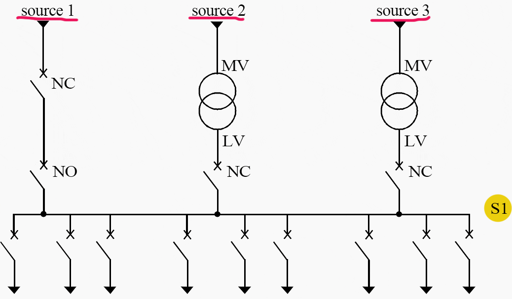
1.4 Triple fed LV switchboards with no coupler
Figure 4 – Triple fed low-voltage switchboards with no coupler


Switchboard S1 has a triple power supply with no coupler via two MV/LV transformers and an outgoing feeder coming from another LV switchboard. During normal operation, the switchboard is fed by two transformers in parallel.
If one or both of the transformers fail, switchboard S1 is fed by the outgoing feeder coming from another switchboard.
Go back to the Contents Table ↑
1.5 Triple fed switchboards with coupler
Figure 5 – Triple fed low-voltage switchboards with coupler


Switchboard S1 has a triple power supply with couplers via two MV/LV transformers and an outgoing feeder coming from another LV switchboard.
During normal operation, the two coupler circuit-breakers are open and switchboard S1 is fed by three supply sources. If one source fails, the coupler circuit-breaker of the associated source is closed and the incoming circuit-breaker of the source that has been lost is opened.
Go back to the Contents Table ↑
2. LV switchboards backed up by generators
2.1 Example #1: 1 transformer and 1 generator
Figure 6 – An example with 1 transformer and 1 generator


During normal operation CB1 is closed and CB2 is open. Switchboard S2 is fed by the transformer. If the main source is lost, the following steps are carried out:
- The mains/standby changeover switch is operated and CB1 is tripped.
- Load shedding, if necessary, of part of the loads on the priority circuit in order to facilitate start-up of the generator.
- Start-up of the generator.
- CB2 is closed when the frequency and voltage of the generator are within the required ranges.
- Reloading of loads which may have been shed during step 2.
Once the main source has been restored, the generator is stopped and the mains/standby changeover device switches the S2 supply to the mains.
Go back to the Contents Table ↑
2.2 Example #2: 2 transformers and 2 generators
Figure 7 – An example with 2 transformers and 2 generators


During normal operation, the coupler circuit-breaker CB1 is open and the mains/standby changeover device is in position CB2 closed and CB3 open. Switchboard S1 is fed by transformer TR2.
If source 2 is lost or there is a breakdown on TR2, the S1 (and part of S2) standby supply is given priority by transformer TR1, after reclosing of the coupler circuit-breaker CB1. The generators are only started up after the loss of the two main supply sources.
The steps for saving the priority circuit supply are carried out in the same way as in the above Example #1.
Go back to the Contents Table ↑
3. LV switchboards backed up by UPS
The main devices that make up a UPS system are shown in Figure 8 and Table 1-1.
Figure 8 – UPS system


Table 1 – Function of different devices making up a UPS system
| Device name | Ref. No. | Function |
| Rectifier – charger | (1) | Transforms the alternating voltage of a supply network into a direct voltage which will:
|
| Storage battery | (2) | Provides a back-up supply to feed the inverter in case:
|
| Inverter | (3) | Transforms the direct voltage from the rectifier-charger or storage battery into three-phase alternating voltage with more severe tolerances than those of the network (supplies an alternating current close to the theoretical sine curve). |
| Static contactor | (4) | Switches over the load supply from the inverter to network 2 (standby) without interruption (no cut due to mechanical switching device changeover time – the switchover is carried out using electronic components in a time < 1 ms). This switchover is performed if the inverter stops working for one of the following reasons:
|
| Manual by-pass | (5) | Manual switch which allows the user to be fed by network 2 (standby), while maintenance is being carried out. Its presence is indispensable when the network frequencies upstream and downstream of the UPS are identical. |
| Insulating transformer | (6) | Provides upstream and downstream insulation when the supply is via network 2. It is especially used when the upstream and downstream earthing systems are different. |
| Manual switches | (7) (8) | Provides insulation of the different parts when maintenance is being carried out. |
| Battery circuit breakers | (9) (10) | Provides insulation of the different parts when maintenance is being carried out. |
Network incoming feeder(s)
The terms network 1 and network 2 designate two independent incoming feeders on the same network:
- Network 1 (or mains) designates the incoming feeder usually supplying the rectifier-charger;
- Network 2 (or standby) is said to be a back-up feeder.
The connection of a UPS system to a second independent network is recommended since it increases the reliability of the system. It is nevertheless possible to have only one common incoming feeder.
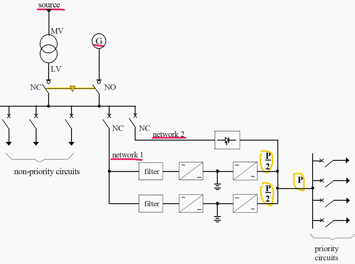
3.1 Example #1
LV switchboard backed up by an inverter, with a generator to eliminate the problem of the limited autonomy of the battery (usually about 15 mn). See Figure 9.
Figure 9 – Low-voltage switchboard backed up by an inverter


The filter allows harmonic currents traveling up the supply network to be reduced.
Go back to the Contents Table ↑
3.2 Example #2
LV switchboard backed up by 2 inverters in parallel with no redundancy. See Figure 10.
Figure 10 – LV switchboard backed up by 2 inverters in parallel with no redundancy


This configuration only allows an overall power capacity above that of a single rectifier/inverter unit. The power P to be supplied is also divided between the two inverters. A fault in one of the units leads to the load being switched to Network 2 without interruption, except when the network is beyond its tolerance level.
Go back to the Contents Table ↑
3.3 Example #3
LV switchboard backed up by 3 inverters, one of which is actively redundant. See Figure 11.
Figure 11 – LV switchboard backed up by 3 inverters, one of which is actively redundant


Let P be the maximum load rating of the priority circuit. Each inverter has a rated power of P/2, which means that when one inverter breaks down, the other two inverters provide the total load power supply. This is referred to as a parallel-connected unit with 1/3 active redundancy.
Go back to the Contents Table ↑
3.4 Example #4
LV switchboard backed up by 3 inverters, one of which is on standby redundancy. See Figure 12.
Figure 12 – LV switchboard backed up by 3 inverters, one of which is on standby redundancy


Inverter 3 is not charged; it is on standby ready to back up inverter 1 or 2 . There is no power cut during switchover due to static contactors c and d. Static contactor e provides back-up via network 2 in case there is a failure on network 1, or the two inverters break down.
This is referred to as a parallel-connected unit with standby redundancy.
Go back to the Contents Table ↑
Source: Protection of Electrical Networks by Christophe Prévé


hii.i am writing from Tanzania. i have tried many times to register for a course but always unsuccessful. Are your courses limited to a certain geographical area or not? thanks in advance
Good presentation for schematic planning of mv/lv distribution system.
Thanks.
This is awesome
Good information here
Very informative. Thank you for writing these articles.
Good stuff. Thank you for this article.
How can I come in touch with Mr. Edvard Csanyi.
Our field is the development of technical software including Electrical engineering
Very educative information