
Beyond voltage, current & interrupting rating
Consideration of all the factors related to proper application of a low-voltage circuit breaker goes beyond voltage, current, and interrupting rating. The performance of a specific type of circuit breaker may be influenced by nonelectrical factors related to the installation environment, such as ambient temperature, humidity, elevation, or presence of contaminants.
 4 important factors related to proper application of a LV circuit breaker
Enclosure type and size, service conditions, loads and their characteristics, outgoing conductors, characteristics of the electrical distribution system, other protective devices on the line side and load side of the circuit breaker under consideration, and even frequency of operation and maintenance should all be taken into account.
For this technical article, application considerations are limited to conditions involving abnormal current and to providing protection and selective coordination under these conditions.
1. Protection
The function of system protection may be defined as the detection and prompt isolation of the affected portion of the system when a short circuit or other abnormality occurs that might cause damage to, or adversely affect, the operation of any portion of the system or the load that it supplies.
Short circuits may be phase-to-ground, phase-to-phase, phase-to-phase-to-ground, three-phase, or three-phase-to-ground. Short circuits may range in magnitude from extremely low-current faults having high-impedance paths to extremely high-current faults having very low-impedance paths.
However, all short circuits produce abnormal current flow in one or more phase conductors or in the ground path. Such disturbances should be detected and safely isolated.
Two types of overcurrent protection are emphasized:
- phase-overcurrent and
- ground-fault.
At the present state of the art, phase-overcurrent conditions are detected on the basis of their magnitudes. Response time is dependent upon the particular overcurrent time-current characteristic (TCC) curve.
Ground-fault currents of a sufficient magnitude may be detected by phase-overcurrent devices. Currents below the minimum current sensitivity of phase-overcurrent devices, such as arcing ground faults, are not cleared.
A separate means (either internal to the circuit breaker or externally mounted) should be provided to detect these low-level arcing ground faults. This means of detection commonly consists of current sensors that monitor each phase and the grounding conductor separately or one current sensor that monitors all phase conductors.
A single current sensor that monitors the ground-fault current in a transformer or generator neutral grounding conductor may be used. Circuit breakers have the advantage of providing a convenient means for opening all phase conductors in response to a signal from either the phase-overcurrent or ground-fault detection device. They have the additional advantage of having the current sensors and logic circuitry located internally within the breaker.
This location minimizes the need to make external connections to control components.
MCCBs are available with various interrupting ratings in the same physical frame size. Selection by frame size or continuous-current rating alone is not sufficient. The interrupting rating should also be considered.
Current-limiting fuses, integrally fused circuit breakers, or current-limiting circuit breakers may be provided to lower the let-through short-circuit current. Curves depicting let-through current and I2t are available from manufacturers to assist in the application of these circuit breakers as shown in Figure 1a and Figure 1b.
An alternate method is the series connection of MCCBs, that is, two MCCBs electrically in series sharing fault interruption duties.
See Figure 3 for an example of a test setup. Selectivity is not provided at any current level where the breaker trip characteristic curves overlap, that is, both circuit breakers trip.
Series-connected ratings should be based on tests and are only valid for the specific circuit breaker types listed in the test reports.
Individual manufacturer’s series-connected ratings may be found in the UL Recognized Component Directory. Fuse and breaker coordinated combinations are also tested by UL and are applicable within their established ratings.
Determination of available fault-current levels, specification of circuit breakers and associated equipment rated for those levels, and inspection to verify that properly rated equipment has been installed satisfy the basic requirement of providing adequately rated equipment for system protection.
Selection of appropriate trip unit functions and their settings to provide protection and coordination is the next consideration.
Basic rules applicable to phase overcurrent protection are as follows:
Rule #1
Select continuous-current ratings and pickup settings of long-time delay characteristics, where adjustable, that are no higher than necessary without causing nuisance tripping and that meet applicable code requirements.
The amount of time delay provided by the long-time delay characteristics should be selected to be no higher than necessary to override transient overcurrents associated with the energizing of load equipment and to coordinate with downstream protection devices.
Rule #2
Take advantage of the adjustable instantaneous trip characteristic on MCCBs and LVPCBs. Set the instantaneous trip no higher than necessary to avoid nuisance tripping. Be sure that instantaneous trip settings do not exceed the maximum available short-circuit current at the location of the circuit breaker in the system.
Rule #3
Provide ground-fault protection in accordance with the NEC, where required. Ground-fault current settings should be set to minimize hazard to personnel and damage to equipment.
Time-delay adjustments of ground-fault protective devices should be set so that ground faults are cleared by the nearest device on the supply side of the ground fault.
2. Selective coordination
When protection is being considered, the performance of a circuit breaker with respect to the connected conductors and load is a primary concern.
To achieve coordination, consideration is also given to the performance of a circuit breaker with respect to other protective devices on the supply side or load side of it.
Generally, coordination is demonstrated by plotting the time-current characteristic (TCC) curves of the circuit breakers involved and by making sure that the curves of adjacent circuit breakers do not overlap, as illustrated in Figure 4.
Often selective coordination is possible only when circuit breakers with short-time delay characteristics are used in all circuit positions except the one closest to
the load.
This setting arrangement is particularly true when little or no circuit impedance exists between successive circuit breakers.
The withstand rating of associated circuit components and assemblies should not be exceeded.
Moving toward the load, on many feeder circuits sufficient impedance exists in the distribution system to appreciably lower the available short-circuit current at the next load-side level circuit breaker.
If the available short-circuit current at this circuit breaker is less than the instantaneous trip setting of the feeder circuit breaker, then selectivity is achieved (see Figure 5 below).
The preceding discussion forms the basis for judging selective coordination between two circuit breakers in series. If the fault current being interrupted by a circuit breaker flows through the line-side circuit breaker for a period equal to or greater than its tripping time, the line-side circuit breaker trips. Under these conditions, the circuit breakers are not selective.
However, if because of impedance between the circuit breakers, the maximum current that can flow during short-circuit conditions is insufficient to initiate tripping of the line-side circuit breaker, selectivity exists.
An alternate method of achieving selective coordination is by selective interlocking of two or more levels of electronic trip units in a system. In a selectively interlocked system, the circuit breaker nearest to and toward the supply side of the fault senses the fault and signals other line-side circuit breakers that it is tripping.
That signal restrains circuit breakers farther to the line-side from reacting until they time out according to their settings. Because it does not receive such a restraining signal from a load-side circuit breaker, the circuit breaker nearest the fault continues to trip with minimum delay.
Some circuit breakers with electronic trip units incorporate an instantaneous override set above their tripping characteristic for self protection. If fault current through the circuit breaker reaches this level, the circuit breaker trips with no intentional delay even in selectively interlocked systems.
This feature should be considered in selectivity studies.
3. Power factor considerations
Normally the short-circuit power factor of a system need not be considered when applying either LVPCBs or MCCBs. This practice is based on the fact that the test circuit power factors on which ratings have been established are considered low enough to cover most applications.
Test circuits with lagging power factors no greater than in Table 1 are used to establish interrupting ratings.
Table 1 – Test circuit power factors
| Available short-circuit current (A, rms symmetrical) | Lagging power factor (%) | ||
| MCCB (a) | LVPCB | ||
| Unfused (b) | Fused (b) | ||
| 10 000 or less | 50 | 15 | 20 |
| 10 001 – 20 000 | 30 | 15 | 20 |
| Over 20 000 | 20 | 15 | 20 |
(a) UL 489
(b) ANSI C37.50
Where the power factor or X/R ratio for a specific system has been determined and is more inductive than the power factor used to establish the interrupting rating, the multiplying factor tabulated in Table 2 may be applied to the calculated, available short-circuit current.
These multiplying factors adjust the short-circuit current to a value equal to the maximum transient offset in the initial half-cycle of short-circuit current flow using the relation in Elements of Power System Analysis, as follows:
where
- t is time and is 0 when voltage is applied,
- α is the electrical angle after t = 0 at which point the circuit is closed,
- θ is the power angle and equals tan–1(ωL / R),
- Z is √(R2 +(ωL)2)
By making the simplifying assumption that the circuit is closed at a time t = 0 when the instantaneous voltage is zero, the following multiplier is derived:
where
- CIRC is the circuit under consideration,
- TEST is the circuit used to test the circuit breaker.
Table 2 – Short-circuit current multiplying factor for circuit breakers
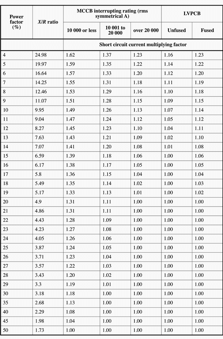
These multiplying factors are based on calculated values for peak currents rather than on laboratory tests. Individual manufacturers may have additional information.
Example
For example, consider a 225 A MCCB with an interrupting rating of 35 000 A to be applied on a circuit with a short-circuit availability of 24 000 A and a power factor of 10%. Select the multiplying factor of 1.13 and multiply the 24 000 A short circuit by it to arrive at the new short circuit of 27 100 A.
In this case, the MCCB is suitable for the 27 100 A short circuit because of its 35 000 A rating.
4. Voltage considerations
The most common industrial and commercial utilization voltage by far is the solidly grounded 480Y/277 V system. Yet, a number of 600 V and 480 V delta systems are in service of both ungrounded and corner-grounded configurations.
Further, a growing number of industrial systems are using resistance-grounded 480Y/277 V systems.
Consider the single fault to ground in View (a) of Figure 6 and the double fault to ground in View (b) of Figure 6 in delta systems. In each case, the voltage across the interrupting pole is just below line-to-line voltage.
The magnitude of the fault depends on the prospective current and the value of the impedances to ground at the respective faults.
Then, consider the resistance-grounded wye system in View (c) of Figure 6. With a single fault to ground, the fault current is severely limited by the resistance grounding connection.
With two faults to ground, voltage across the interrupting pole is at some value between phase voltage and line voltage. Again, the magnitude of the fault depends on the prospective current and the value of the impedances to ground at the respective faults.
For the systems shown in Figure 6, straight-rated (or delta-rated) circuit breakers should be used. Referring to Table 3 and testing standards, it is known that each circuit breaker pole is tested at phase voltage at full prospective current as part of the three-phase test.
Also, each pole is tested individually at line voltage with test currents indicated in Table 3. When system conditions are beyond these test values, use of MCCBs tested specifically for cornergrounded delta systems and use of LVPCBs are options.
Table 3 – Single-pole short-circuit test values for MCCBs
These test values are the minimum required for certification to UL 489. They are not marked ratings and are printed here to aid the system designer who may need them for single-phase short-circuit analysis. Single-pole circuit breakers are tested at values equal to their interrupting ratings.
Table test values are the minimum required for certification to UL 489. They are not marked ratings and are printed here to aid the system designer who may need them for single-phase short-circuit analysis. Single-pole circuit breakers are tested at values equal to their
interrupting ratings.
Table 4 is provided as a guide for applying the appropriate voltage rating of the MCCB to each system.
Table 4 – MCCB voltage rating by system configuration
| System configuration | Three-pole MCCB voltage rating | ||||
| Voltage | Grounding | 480Y/277 | 480 | 600Y/347 | 600 |
| 480Y/277 | Solid | • | • | • | • |
| 480Y/277 | Resistance | • (a) | • | ||
| 480 | Ungrounded | • | • | ||
| 480 | Corner ground | • (a) | • | ||
| 600Y/347 | Solid | • | • | ||
| 600 | Ungrounded | • | |||
| 600 | Corner ground | • | |||
(a) Codes and standards allow 480 V rated MCCBs in these applications. Some manufacturers provide MCCBs specially rated for the corner-grounded delta system to satisfy user preference. These ratings may also be applied to resistance-grounded wye systems. LVPCBs are also an option.
Individual poles of multipole MCCBs are tested at short-circuit levels indicated in Table 4 for all values of multipole interrupting ratings. These tests are in addition to multipole tests in which the individual poles are required to interrupt under transient conditions that are more demanding than single-phase tests of the same pole at phase voltage.
5. Conclusions
The following considerations apply to low-voltage circuit breakers for system protection:
- They combine a switching means with an overcurrent protective device in a compact, generally self-contained unit
- No exposure to live parts is involved during operation when installed in an approved enclosure.
- They are resettable. Normally after tripping (and removal of the fault or overload that caused tripping), service may be restored without replacing any part of the assembly.Inspection of the circuit breaker assembly after fault current interruption is required to verify suitability to return the circuit breaker and/or other parts of the system to service. Inspection of the circuit breakers may require replacement of fuses or fuse assemblies after interruption of high-magnitude fault currents.In LVPCBs, most designs allow for replacing components, such as contacts or arc chutes, using instructions from the manufacturer.
- They provide simultaneous disconnection of all phase conductors.
- High short-circuit interrupting ratings, the availability of current-limiting circuit breakers, and series-connected interrupting ratings permit application on systems with high available fault currents.
- The advent of highly complex and technologically advanced electronic trip units has increased circuit breaker versatility and made selective coordination easier.
- Selection of MCCBs should include consideration of interrupting rating because more than one interrupting rating may be available in the same frame size.
- Selective coordination of ground-fault protective devices requires time-delay and pickup adjustments and may be enhanced by the presence of adjustments that provide inverse TCCs.
Source // IEEE Recommended Practice for Protection and Coordination of Industrial and Commercial Power Systems
Related electrical guides & articles


Edvard Csanyi
Hi, I'm an electrical engineer, programmer and founder of EEP - Electrical Engineering Portal. I worked twelve years at Schneider Electric in the position of technical support for low- and medium-voltage projects and the design of busbar trunking systems.I'm highly specialized in the design of LV/MV switchgear and low-voltage, high-power busbar trunking (<6300A) in substations, commercial buildings and industry facilities. I'm also a professional in AutoCAD programming.
Profile: Edvard Csanyi

Dear sir How much current in 3 phase 440 voltage
Boa noite senhores, gostaria de seber sobre investimentos no dominio da electricidade visto que Angola tem muito que apreder sobre esta materia. Solicito projetos com viabilidade no sector de infrastruturas e, construçºao de barragem em Angola e paises da SADC, com orçamentos e modalidades de pagamentos. Obrigado.
Dear Edvard,
Any relevante influence of frequency (50/60 Hz)?
Thanks in advance
Regards
Hello, Rodrigo. We are often install IS control cables on the rig control room. Could you advise if termination IS control cable’s Electro Magnetic Interference (EMI) screening film should be terminated at the gland of control panel or at the termination point of the cable at the terminal?
Many thanks ,
Egor Gouzenko
This is a very good platform to acquire technical knowledge and is fantastic. Carry on doing good.
Excellent Article on LV. shall be obliged if you can publish similar on MV
Great. Clear. Complete. Easy to use.
Congratulations. Thank you.
Very useful information, it has eased my troubles on LV and MV
Excellent article with very useful information on low power factor systems. Thank you for posting this.
es un articulo muy completo sobre los factores a considerar en la selctividad de protecciones.
Gracias
Very good considerations ! Thank you.