
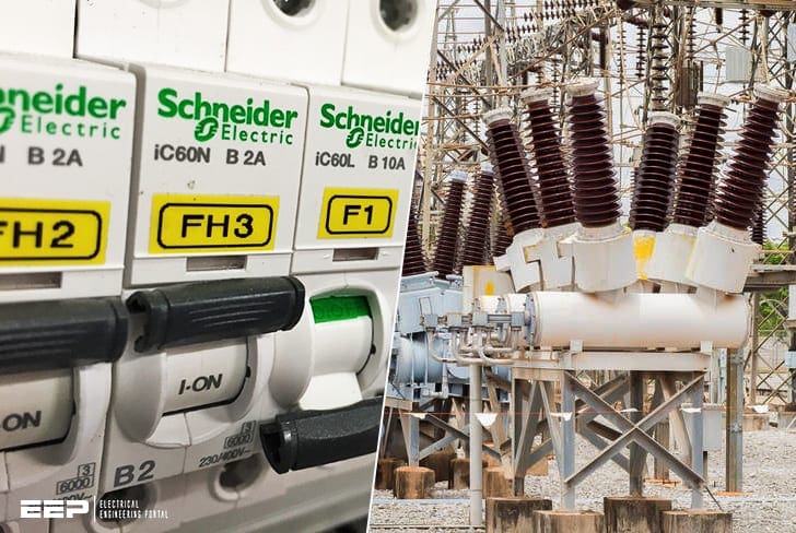
Many different circuit breakers
This technical article discusses two important circuit breaker classifications – by voltage level (from low to medium and high voltage) and secondly by technology (extinguishing method or medium that insulates the breaker contacts.
 Main types and technologies of circuit breakers (from 1000 V MCB to 1000 kV dead tank breaker)
- Voltage levels of circuit breakers:
- High voltage (above 50 kV through 1200 kV)
- Medium voltage circuit breaker (1000 V through 50 kV)
- Low voltage circuit breaker (0 – 1000 V)
- Circuit breakers technologies:
- CB usage and comparison
- Air / Gas:
- Vacuum
- Oil (Bulk oil and Minimum oil)
Circuit breakers by voltage level:
High voltage (above 50 kV through 1200 kV)
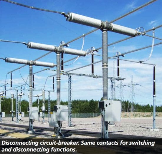
1. Disconnecting Circuit Breaker (DCB)
A Disconnecting Circuit Breaker (DCB) is a high voltage circuit breaker, replaces the conventional combination of circuit breaker and separate disconnectors. The disconnecting function is integrated in the breaking chamber.
That means that the circuit breaker fulfills all requirements for a circuit breaker as well as for a disconnector.
The advantage with the DCB is that it eliminates a separate disconnector switch, which also reduces the size of the substation. One disadvantage with the DCB is that the whole bus bar has to be taken out of service when performing maintenance on the DCB, since one side of the DCB will always remain energized.
2. Live-tank circuit breaker
Live tank breaker is used in high voltage levels. On live-tank circuit-breakers, the interrupter chamber is isolated from the ground by an insulator which can be either of porcelain or of a composite material, and is at high potential. The voltage level determines the length of the insulators for the interrupter chamber and the insulator column.
A further feature of live-tank circuit breakers are the comparatively small gas compartments. The advantage of the low gas volume is that there is a reduction in the amount of gas maintenance work.

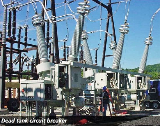
3. Dead-tank circuit breaker
Dead-tank is a high voltage circuit breaker. The distinguishing feature of dead-tank technology is that the interrupter chamber is accommodated in an earthed metal housing. With this design the SF6 gas filling the tank insulates the high voltage live parts of the contact assembly from the housing.
Outdoor bushings connect the interrupter chamber with the high-voltage terminals.
The dead tank circuit breaker has an advantage in case of earth-quakes!
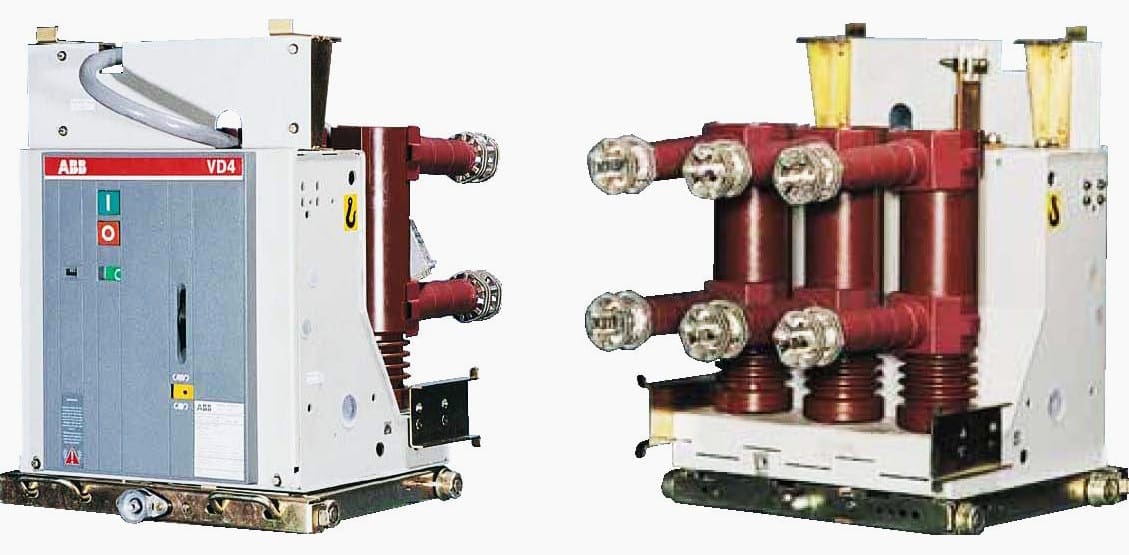
4. Medium voltage circuit breaker
Medium voltage circuit breakers cover voltages from 1000 V up to 50 kV. The term ‘medium voltage’ has come to be used for the voltages required for regional power distribution that are part of the high voltage range from 1kV AC up to and including 52kV AC.
In power supply and distribution systems, medium voltage circuit breakers are installed in:
- Power stations, for generators and station supply systems.
- Transformer substations of the primary distribution level (public supply system or systems of large industrial companies), in which power supplied from the high voltage system is transformed to medium voltage.
- Local supply, transformer or customer transfer substations for large consumers (secondary distribution level), in which the power is transformed from medium to low voltage and distributed to the consumer.
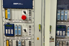
5. Low voltage circuit breaker
Low voltage circuit breakers types are common in domestic, commercial and industrial applications up to 1000 V AC. A Molded Case Circuit Breaker (MCCB) can be rated up to 2500 A. They are thermal or thermal-magnetic operated. These CBs are often installed in draw-out enclosures that allow removal and interchange without dismantling the switchgear.
Some large MCCBs are remotely operated by electrical motors, often part of an automatic transfer switch system for standby power.
Circuit breakers technologies
CB usage and comparison
Circuit breakers can mainly be divided into three groups depending on medium that encloses (insulates) the breaker contacts. In one group, it is air or other gas, in the second vacuum and in the third oil.
- Air / Gas:
- Air circuit breaker (ACB)
- Air blast
- sF6 breaker
- Vacuum
- Oil:
- Bulk oil
- Minimum oil
The SF6 insulated circuit breakers are more or less the only installed type within transmission networks today, mainly due to its relative high total rating and characteristic in relation to its price. However, with new improvements with vacuum breaker design they are also becoming more common at the lower voltage ranges of the transmission networks.
Today they can handle voltages up to 252 kV but are still very expensive.
The vacuum breakers are more commonly installed at system voltage levels of 70 kV and below. Both the SF6 and vacuum circuit breakers are very common in today’s distribution networks.
AIS or GIS substations?
Substations are often built as air-insulated switchgear (AIS), using open air as insulating medium between the different phases and devices.
Gas-insulated switchgears (GIS) are designed and assem- bled by a combination of standardized function modules such as circuit breakers, disconnectors, earth-switches, current and voltage transformers, and supplementary modules.
Air / Gas
1. Air circuit breakers (ACB)
ACBs can be used both as circuit breakers of low voltage electrical distribution systems and for protection of electrical equipment in facilities and industries.
A common breaking principle is to use the magnetic eld, created by the current through the ACB, to force the arc to- wards insulating lamells. As the arc goes further in between the lamells eventually the distance to maintain the arc is exceeded and it is extinguished.
2. Air blast circuit breakers
The air blast circuit breakers came into use in the 1930s and became be the common circuit breaker on high voltage and very high voltage applications. The robust designs were reliable and robust but noisy. Many breaks are needed for high voltages and they are commonly found with opening resistors.
Air is compressed in a reservoir up to 14 bar. The contacts are opened by air blast produced by opening a valve. The compressed air is released and directed towards the arc at high velocity. The air blast cools the arc and sweeps the arc- ing products away. This increases the dielectric strength of the medium between contacts and prevents re-establishing the arc.
The arc is extinguished and the current is interrupted. The short arcing time, compared with oil CB, gives low impact on the main contacts.
3. SF6 circuit breaker
Sulphur hexa fluoride (SF6) is an inert, heavy gas having good dielectric and arc extinguishing properties. The dielectric strength of the gas increases with pressure. It is an electro-negative gas which means that the free electrons are attracted to the gas and are not free to move.
The consequence of this characteristic is a high dielectric strength.
Arcing can produce a number of more or less toxic decomposition by-products that places high demands on recycling and disposal of the gas.
There are two main types; puffer and self-blast. The puffer type creates the gas pressure using a piston pump whereas the self-blast takes advantage of the pressure created by the heat from the arc. The advantage of the puffer type is that it has good breaking properties for all current levels.
The disadvantage is that it requires more mechanical force to operate, requiring a bigger operating mechanism. The advantage of the self-blast is that it requires up to 50% less energy than the puffer breaker to operate but it has less good breaking properties.
Vacuum circuit breaker
Vacuum breakers are used up to 70 kV. Because there is no gas to ionize to form the arc, the insulating gap is smaller than an in other circuit breakers. An arc does form from the vaporized contact material. The insulation distance in a vacuum breaker is about 11-17 mm between plates. Normally there is one break per phase but there can be two interrupters in series.
Other advantages with vacuum breakers are their relatively long operational life time and their relatively limited impact on the environment since they are designed without poisonous gases and relative few components.
Vacuum circuit breakers also suffer less wear on the main contact than air and oil circuit breakers.
Oil circuit breakers
Bulk oil
The current interruption takes place in oil tank. The oil cools and quenches the arc and is also insulating. This type has mainly been used at the distribution level and demands a lot of maintenance on the main contacts.

Minimum oil
It is used in transmission and substation and require small amount of oil and it operates very fast.
References //
- Circuit breaker testing guide by MEGGER
- NRC Medium Voltage Circuit Breaker Training
Related electrical guides & articles


Edvard Csanyi
Hi, I'm an electrical engineer, programmer and founder of EEP - Electrical Engineering Portal. I worked twelve years at Schneider Electric in the position of technical support for low- and medium-voltage projects and the design of busbar trunking systems.I'm highly specialized in the design of LV/MV switchgear and low-voltage, high-power busbar trunking (<6300A) in substations, commercial buildings and industry facilities. I'm also a professional in AutoCAD programming.
Profile: Edvard Csanyi

It is highly beneficial.
good job
Very good job done. But, please add pdf saving function for each of these technical abstracts or educational texts.
Best Regards,
Tayfun Konur – Sen. ELC. POWER ENG. – ISTANBUL – TURKEY
Hi Tayfun, saving technical article in PDF format is available only to premium members. More information about Premium Membership you can find here:
https://electrical-engineering-portal.com/premium-membership
there has never been a very clear explanation like yours, thanks
Muchas gracias señor Edvard Csanyi su presentación es muy didáctica
Thanks so much Mr. Edvard .your work is so inspiring and enriching . I appreciate every bit of it.
Hi Edvard, a good debriefing for different device/technology protection
Congratulations for your job.
Thank you Carlos!