
Residual currents (earth fault)
The measurement of the earth fault or residual currents on a distribution system feeder can be done by the so-called summation connection, where the three current transformers, one in every phase, are connected and the summated current is brought to the inputs of an earth fault protection relay.
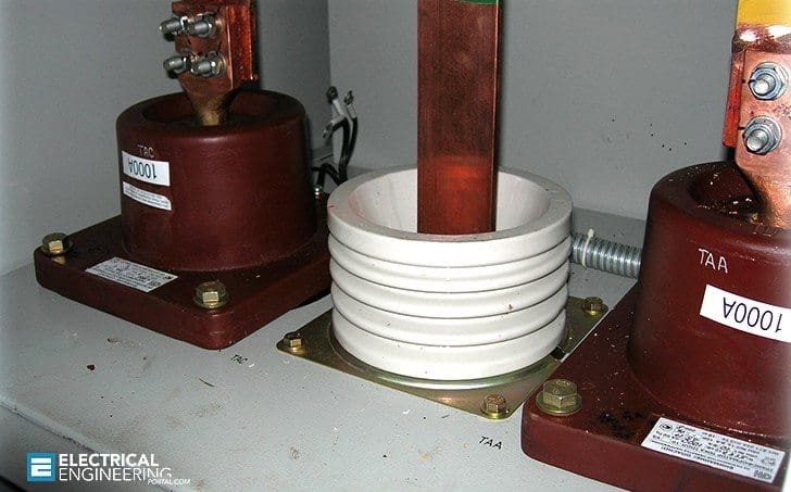 Measurement of residual currents on a distribution feeder
This is a convenient method for cases where the level of the earth fault current is relatively high, i.e. directly earthed systems.
When the level of the fault current to be measured starts to decline heavily, the measurement sensitivity and accuracy that can be reached with this summation connection is no longer sufficient. The measurement accuracy is affected by the fact that the three different current transformers, even with similar core data, start to introduce different kind of errors when it comes to ratio and phase displacement.
These errors are summated together in the summation connection, and in the worst case they are cascading on top of each other. The sensitivity is affected by the fact that current transforming ratio of the phase current transformers is mainly selected based on the maximum load currents, whereas the anticipated earth fault currents can be only some fractions of those.
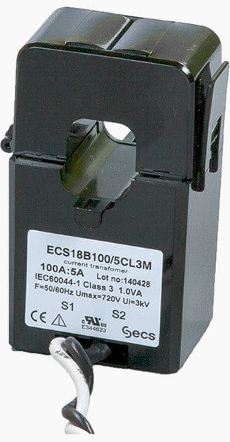
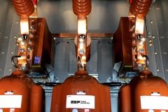
To overcome the accuracy and sensitivity requirements with low (earth fault) residual currents, a cable (or busbar), also called a window-type, current transformer can be utilized. Following figure describes the installation.
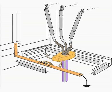
In the figure above, a cable current transformer is utilized for measuring the residual (earth fault) current of an outgoing three-phase cable feeder. The CT type used is a one that can be installed even after the medium voltage power cable installation is done, by opening the bolted connections and separating the CT into two parts.
The suitable current transforming ratio of the cable current transformer is depending on the actual anticipated earth fault current levels.
As an example, the ratio of 70/1A is commonly used for earth fault protection in Finland with unearthed and resonant earthed systems. The cable current transformer can also have several ratios by utilizing different tappings in the secondary side, as shown below.
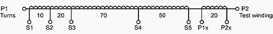
When the earth fault protection relay is connected to a certain secondary tapping of the CT, the remaining tappings should not be shorted. This applies also to the test winding tappings. On the other hand, if the cable CT has several cores utilizing separate iron cores inside the CT, each of the cores has to either be connected to a secondary device or short-circuited and earthed.
Reference // Distribution Automation Handbook by ABB
Related electrical guides & articles


Edvard Csanyi
Hi, I'm an electrical engineer, programmer and founder of EEP - Electrical Engineering Portal. I worked twelve years at Schneider Electric in the position of technical support for low- and medium-voltage projects and the design of busbar trunking systems.I'm highly specialized in the design of LV/MV switchgear and low-voltage, high-power busbar trunking (<6300A) in substations, commercial buildings and industry facilities. I'm also a professional in AutoCAD programming.
Profile: Edvard Csanyi

substation tests (comissioning)
A example for use in isolated electrical system is the “ Difference connection -special CT”, used for Sensitive Earth Current Protection to generator Gas Turbine.
Hello,
We have a 3 core cable in 6 kv system.
In 6 kv switchgear for earth fault protection we use a core ballance ct in bottom of gland plate,
Armour & shiled of this cable connected to earth in above of CT (inside of feeder) , and in transformer side (6/0.4 kv) only armour of this cable connected to earth.
is this conne tion correct for detection of earth fault?