
Medium voltage switching equipment
This technical article covers the medium voltage switching equipment intended mainly for primary substation installations. The target is to give some basic knowledge and difference between four main piece of MV switching equipment, especially in the view of distribution automation concept. Both indoor and outdoor installation alternatives are presented.
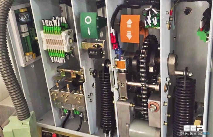 4 medium voltage switching equipment for primary substation installations (on photo: Vacuum MV circuit breaker mechanism)
The indoor installation refers to the switching equipment used in metal-enclosed medium voltage switchgears. Main focus with the discussions is on the air-insulated solutions.
The following switching equipment will be covered:
1. Circuit Breakers
A circuit breaker must be capable to make and break all the load and fault currents that it might be subjected to at the specific installation. Key factors with circuit breakers’ performance are:
- Opening (break) and closing (make) time,
- Rated continuous current-carrying capability,
- Rated dynamic short circuit withstand capability,
- Rated thermal short circuit withstand capability,
- Maximum operation voltage and
- Rated operation sequence.
Earlier, the small-oil circuit breakers were common on medium voltage indoor installations and air-blast or oil breakers in outdoor installations. Today, these technologies have been replaced with SF6 gas and vacuum technologies. SF6 gas is dominating with outdoor installations, whereas with indoor installations both vacuum and SF6 gas technologies are utilized.
With live tank breakers, the outer surface of the breaking chamber is not earthed and is under primary voltage influence, thus “live.” With dead tank breakers, the outer surface of the breaking chamber is earthed, thus “dead.”
Dead tank breakers are generally only available for outdoor installations from 33 kV upwards.

The circuit breakers for outdoor mounting are generally fixed ones, whereas the breakers intended for indoor use, as a part of metal-enclosed switchgears, are generally mounted on a truck, although exceptions exist.
The actuating system, operation mechanism, is the unit within the circuit breaker that supplies the power and movement for the primary contacts to close or open. Depending on the arc-extinguishing principle the breaker utilizes, the needed power is different.
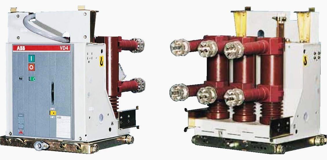
With modern design SF6 and vacuum breakers, the power need is relatively low. There are a number of different actuating systems available.
The following actuator types are commonly available:
- Charged spring operation mechanism (spring)
- Pneumatic (compressed air)
- Hydraulic (compressed air)
- Hydraulic spring (Metallic spring bellows)
- Magnetic (capacitor)
Means of storing the energy with different actuator types is shown in the brackets. The control of the actuator within a circuit breaker is carried out by utilizing electrical commands, either locally or remotely. The electrical signal activates the shunt trip or closing coils that in turn will activate the actuator, either closing or opening the breaker.
Normally, also a mechanical control of the actuator to open the breaker is provided locally at the breaker, that is, the emergency trip. The traditional shunt coils can be replaced with an electronic circuit for actuator control. The important breakers, like the main power transformer feeders, at the higher distribution voltage levels are often equipped with duplicated tripping coils or corresponding electronic circuits.
For outdoor installations with a voltage level of 66 kV and up, the modern technology provides a possibility to combine the functionality of circuit breaker, disconnector and earthing switch into one physical component called disconnecting breaker (see this video).
The circuit breaker construction has been modified to fulfill the disconnector requirements in the open position. The earthing switch is separately mounted on the same disconnecting breaker unit and interlocked with the main contacts position.

Protection and control
The fast and reliable operation of the circuit breaker is of paramount importance for the complete distribution system. Therefore the operation of the breaker is closely monitored by the protection and control system, that is, the IEDs and the upper-level systems.
The modern IEDs are typically monitoring the following issues:
- Trip circuit continuity (both in open and closed positions)
- Breaker travel time (IED for fixed limits and upper-level systems for trends)
- Breaker stress (I2t, in the view of maintenance intervals)
- Breaker’s response to trip commands (breaker failure protection)
- Gas pressure or density in case of SF6 type of breakers
- Actuator’s energy storage charging current, like motor current with charged spring operation mechanism
Switching reactive loads, like shunt capacitors and unloaded power transformers, can be sometimes a source for undesired overvoltages or overcurrents.
With three-phase breakers, one of the phases is monitored by the device and the other phases have a 120-degree mechanical delay in their operation, thus the breaker has to be specifically tuned for this kind of operation.
2. Contactors
Medium-voltage contactors are used instead of circuit breakers typically in industrial indoor metal-enclosed switchgear applications up to 12 kV where the switching frequency is very high, like certain motor feeders for pumps and fans.
The contactor is either the vacuum type or the SF6-insulated one.
In such cases, the IED protection functions’ settings will be coordinated with the contactor’s breaking capability and the protective fuse characteristics.

3. Switch Disconnectors
The switch disconnectors, also called load disconnectors, are used either as fixed or truck- mounted switching devices in metal-enclosed indoor switchgears. The switch disconnector has a rated breaking capacity up to its rated nominal current, that is, the maximum load current, and it provides visual separation point fulfilling the requirements for isolation distance.
The making capacity normally corresponds to the short circuit rating of the switch. The switch disconnectors can be either air-insulated or gas-insulated ones. The unit can be further expanded with series HRC fuses and with line-side earthing disconnector.

The operation mechanism is typically of the charged spring type, where the energy needed for closing or opening operation is manually charged into the spring. The closing or opening sequence is initiated using local mechanical control. The unit can be equipped with electrical trip shunt coil, enabling a remote opening control of the main switch.
4. Disconnectors
Disconnectors are mechanical switching devices which provide an isolating distance and a visual separation gap in the open position. They are capable to open or close a circuit if both the negligible current is switched and there is no significant difference in the voltage between the terminals of the poles.
Currents of negligible quantity have values ≤ 0.5 A. Examples are capacitive charging currents for bushing, busbars and connections, very short lengths of cable and currents of voltage transformers. Disconnectors can carry rated currents under operating conditions continuously and under abnormal conditions, such as short circuit, based on their rated short circuit withstanding capability.
Earlier, a common practice was to employ overall substation-wide mechanical interlocking schemes, like a system called “castle-key” interlocking. Today, a common practice is to use overall electrical interlocking schemes, supported by mechanical interlocking between the switching equipment mounted on the same physical construction.
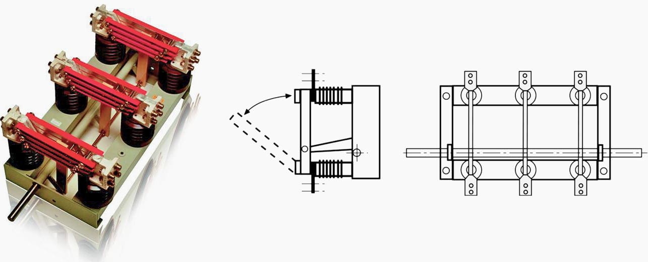
The classic design is the knife contact (single-break) disconnector, as shown in the following figure. Other designs intended mainly for outdoor use exist, like double break, single-center break and pantograph. In medium-voltage indoor switchgear installations, the need for separate disconnectors has become less common with the increasing use of withdrawable circuit breakers and switch disconnectors.
With gas insulated switchgears (GIS) and outdoor installations, the disconnector is still a very common component.
Earthing switches are used for earthing and short-circuiting de-energized station components. Earthing switches can at their rated short circuit withstand currents under abnormal conditions, such as a short circuit, but they are not required to carry continuous load currents.
The earthing switch can be also equipped with spring-charged closing device, making it capable of making fault currents, like in a case where the earthing switch is closed against an energized feeder.
In general, earthing switches are combined with the adjacent disconnectors or switch disconnectors to form one unit. However, earthing switches can also be installed separately.

Where:
- Rotating base
- Frame
- Post insulation
- Rotating head
- Contact arm
- High voltage terminal
- Mechanism
- Earthing switch
Reference // Distribution Automation Handbook by ABB
Related electrical guides & articles


Edvard Csanyi
Hi, I'm an electrical engineer, programmer and founder of EEP - Electrical Engineering Portal. I worked twelve years at Schneider Electric in the position of technical support for low- and medium-voltage projects and the design of busbar trunking systems.I'm highly specialized in the design of LV/MV switchgear and low-voltage, high-power busbar trunking (<6300A) in substations, commercial buildings and industry facilities. I'm also a professional in AutoCAD programming.
Profile: Edvard Csanyi

Well done, once metal closed
is utilized by indoor sf6 or vacuum circuit breaker, is it essential for withdrawable type to be used as preferable option or fixed type might be another permissible way..
Edvard, t:hanks for an interesting article. The text might br improved at one point: one line of the section on earthing switches reads “Earthing switches can at their rated short circuit current…” It might be better to say “Earthing switches can survive their rated short circuit current…” (In practice, if an earthing switch has to do this, it’s probably an operator error & we shouldn’t be surprised if the switch needs replacing afterwards.)