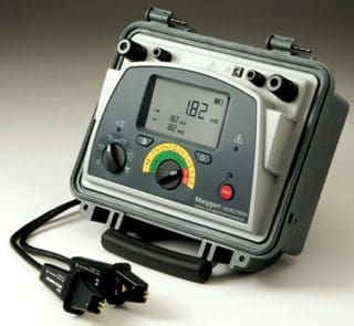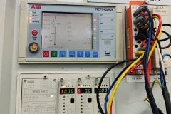
The insulation resistance test (meggering) is of value for future comparison and also for determining if the transformer is to be subjected to the applied voltage test.The winding insulation resistance test is a DC high voltage test used to determine the dryness of winding insulation system. The test measures the insulation resistance from individual windings to ground and/or between individual windings.
The measurement values are subject to wide variation in design, temperature, dryness and cleanliness of the parts. This makes it difficult to set minimum acceptable insulation resistance values that are realistic for wide variety of insulation systems that are in use and performing satisfactorily. If a transformer is known to be wet or if it has been subjected to unusually damp conditions, it should be dried before the application of the applied voltage test.
Low readings can sometimes be brought up by cleaning or drying the apparatus. The insulation resistance test should be performed at a transformer temperature as close as possible or at 20 °C. Test conducted at other temperature should be corrected 20°C with the use of temperature correcting factor.
Duration of the test voltage shall be 1 minute. In the absence of manufacture’s recommended values, the following readings may be used. Refer to Table 1.
Table 1 – Transformer Insulation Resistance Acceptance Testing
| Winding Insulation Class, kV | Insulation Resistance, MΩ* |
| 1.2 | 600 |
| 2.5 | 1000 |
| 5.0 | 1500 |
| 8.7 | 2000 |
| 15 | 3000 |
* Normally dried transformers may be expected to have readings 5 to 10 times the above minimum values.
Important Notes:
- Table 1 was sourced from IEEE C57-94-1982 Recommended Practice for Installation, Operation and Maintenance of Dry-type General Purpose Distribution and Power Transformer. Table 6 differs from NETA Table 100.5 figures for transformer Insulation Resistance Acceptance Testing values. There is no industry consensus for satisfactory values.
- Other references noted a general rule of thumb for acceptable insulation values at 1MΩ per 1kV of nameplate rating plus 1MΩ.
- Under no condition should the test be made while the transformer is under vacuum.
- The significance of values of insulation resistance test requires some interpretation depending on design, dryness and cleanliness of the insulation involved. It is recommended that the insulation resistance values be measured during periodic maintenance shutdown and trended. Large variation in the trended values should be investigated for cause.
- Insulation resistance may vary with applied voltage and any comparison should be made with the same measurements at the same voltage and as close as possible to the same equipment temperature and humidity as practically possible.
Insulation Resistance Test Procedure:
- Isolate the equipment, apply working grounds to all incoming and outgoing cables and disconnect all incoming and outgoing cables from the transformer bushing terminals connections. Disconnected cables should have sufficient clearance from the switchgear terminals greater that the phase spacing distance. Use nylon rope to hold cable away from incoming and outgoing terminals as required.
- Ensure the transformer tank and core is grounded.
- Disconnect all lightning arresters, fan system, meter or low voltage control systems that are connected to the transformer winding.
- Short circuit all winding terminals of the same voltage level together.
- Perform a 1 minute resistance measurements between each winding group to the other windings and ground.
- Remove all shorting leads after completion of all test.
Table 2 – Insulation Resistance Test Connections for Two Winding Transformer
| Test No. | Single-phase transformer | Three-phase transformer |
| 1 | High voltage winding to low voltage winding and ground | High voltage winding to low voltage winding and ground |
| 2 | High voltage winding to low voltage winding | High voltage winding to low voltage winding |
| 3 | High Voltage winding to ground | High voltage winding to ground with low voltage winding to guard |
| 4 | Low Voltage winding to high voltage winding and ground | Low voltage winding to high voltage winding and ground |
| 5 | Low voltage winding to ground | Low voltage winding to ground and high voltage winding to guard |


Hi
A transformer megger reading is 602Mega Ohms at 42 degrees celcius, 20MVA, 88;22KV is the meggaaer results acceptable
Not that it really matters but picture shows a microohm meter and not a insulation resistance tester…
Hi
I am hope to be good
when I have seen this site, I am very happy, because subjects of this site are useful and applicable
good luck
What is the ideal or acceptable values in Ductor Testing of a busbar connections is it in micro ohms or milli ohms?
What is the ideal dc voltage sitting in Megohm testers for 15kVA, 460/230v transformer and what is the acceptable megohm result?
Per NETA standard, 1kV dc test voltage and minimum reading should be 500 MOhm. Also, if ambient temperature is not 20 deg C, correction factor needs to be applied in getting the right IR reading.
Is there a way to measure the ir of thansformer without removing the hv and lv cables from the bushings??
First of all thanks for your shared information and for your efforts but i have a question
is tests ( 1&3) and (4&5) are the same?
What are the minimum and maximum resistive values for a 315kva and 500kva transformer?
so technically informative and knowledge updating site
Is it good not if we dont short circuited the winding terminals of the transformer if we are doing insulation testing? Need help pls. Thank you
The test Voltage all over the winding must be the same, tha is the importance of the shortcircuit. If you don’t make this conection you can have 10 kV in one point and 7 kV in the other side of the winding, to give you and example. Good luck!
GOOD INFORMATION