
Power interruptions & what can be done
Distribution systems are basically insecure – failure of a major component always leads to customer interruptions. So, what can be done? Reliable distribution systems minimize this impact by allowing faults to clear themselves, by minimizing the number of customers affected by protection device operations and by quickly restoring customers through system reconfiguration.
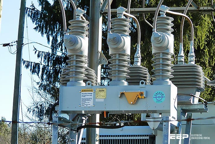 Minimizing failure impact in distribution systems by allowing faults to clear themselves (on photo: New Kyle Nova 38 reclosers recently installed at the Wall St. 12K substation in Colchester, CT. This is a newer type vacuum insulated model, as opposed to oil-insulated. Credit: Jim via Flickr)
A clear understanding of this process is critical to understanding distribution reliability.
- Fault on Main Feeder
- Fuse Saving
- Fuse Clearing
- Recloser / Fuse Coordination
- Automatic Sectionalizers
1. Fault on Main Feeder
(Fault on line L5)
For the system represented in Figure 1, consider a 3-phase fault occurring on line section L5. Fault current immediately flows from subtransmission lines to the fault location, causing a voltage drop across transformer T1 and resulting in voltage sags for customers on L9-L12.
Customers on L2 through L4 experience sags of increasing severity and the voltages on L5 and L6 are nearly zero.
Fault current causes breaker B1 to trip open. A reclosing relay then closes the breaker. If no fault current is detected, the fault has successfully cleared and all customers downstream of B1 experience a momentary interruption.
If fault current persists, B1 trips and recloses again. After several reclosing attempts, B1 will lock out (remain open) and all customers downstream of B1 will experience a sustained interruption. After B1 sends an alarm to the system operator and customer trouble calls are received, the on-duty system operator dispatches a crew to locate the fault.
Because of the long repair time, the operator instructs the crew to open S56 and close S67. Customers on L6 are restored and are now being supplied by Substation 2 rather than Substation 1.
The first switching step is called upstream restoration and the second switching step is called downstream restoration. The entire switching sequence is called system reconfiguration.
After the fault is repaired, the crew returns the system to its pre-fault state.
2. Fuse Saving
(Fault on line L4)
Now consider a fault on L4. An instantaneous relay quickly opens B1 before the fuse element in F4 starts to melt. If the fault is cleared when B1 recloses, all customers downstream of B1 experience a momentary interruption.
If not, a coordinated time-overcurrent relay allows F4 to blow before B1 trips again.
Customers on L4 experience a sustained interruption and customers on the rest of the feeder experience a momentary interruption.Fuse saving is also referred to as,feeder selective relaying.
3. Fuse Clearing
(Fault on line L4)
Fuse saving schemes temporarily interrupt an entire feeder for all faults occurring on fused laterals. To reduce the high number of resulting customer momentary interruptions, utilities often block breaker instantaneous relays.
Consider the same fault on L4. Instead of an instantaneous relay quickly opening B1, a coordinated time-overcurrent relay allows F4 to clear before B1 opens.
L4 experiences a sustained interruption, and the rest of the feeder is prevented from experiencing an interruption.
In addition, customers that are prevented from experiencing a momentary interruption will still see a voltage sag that can have a similar impact on sensitive loads.
4. Recloser / Fuse Coordination
(Fault on line L2)
Consider a fault on L2 with fuse saving enabled. Since the fault is near the substation, the impedance of T1 limits its magnitude. T1 has a base rating of 20 MVA at 12.47 kV and an impedance of 10%.
This results in a fault current of:
The instantaneous relay on B1 will detect the fault in about 4 ms, but the breaker requires about 80 ms to physically open and clear the fault.
Meanwhile, 9.26 kA of current will melt one of the slowest available fuses (200T) in about 40 ms. Since the circuit breaker cannot beat the fuse and clear the fault, customers on L2 will experience a sustained interruption and all other customers on the feeder will still experience a momentary interruption.
Another alternative is to use automatic sectionalizers.
5. Automatic Sectionalizers
(Fault on line L9)
Consider a fault on L9 with a magnitude of 10kA – too high to coordinate a fuse saving strategy. As an alternative, an automatic sectionalizer AS9 is used to protect the lateral.
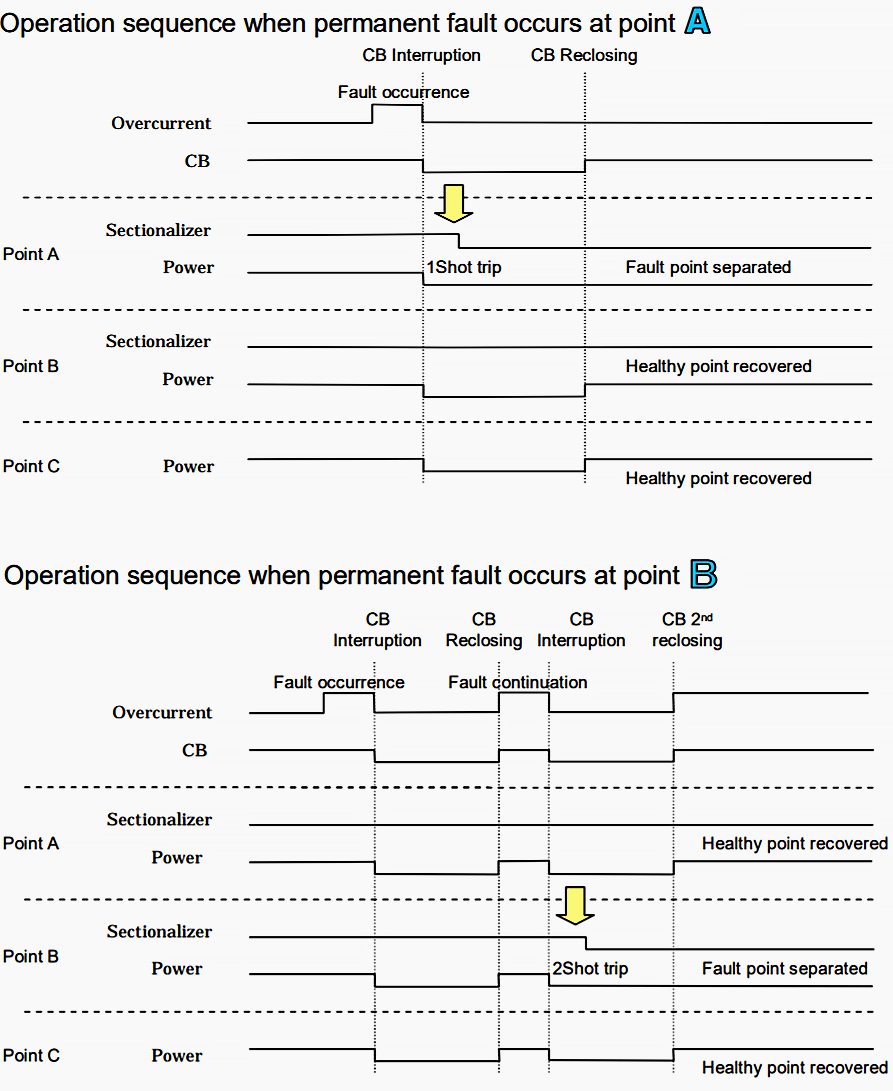
The automatic sectionalizer detects the fault and increments its counter to C=1. B1 opens and recloses to allow the fault a chance to clear itself. If the fault persists, the AS9 counter will increment to C=2. When its counter reaches a pre-set value, AS9 will automatically open the next time B1 opens.
The fault is isolated, Bl closes a last time, and customers experience interruptions equivalent to a fuse saving scheme.
Because sectionalizers use upstream devices to interrupt faults, they can be used wherever coordination issues become a problem.
A distribution system fault impacts many different customers in many different ways.
In general, the same fault results in voltage sags for some customers, momentary interruptions for other customers, and varying lengths of sustained interruptions for other customers depending on how the system is switched and how long it takes for the fault to be repaired – all critical to distribution system reliability.
Sectionalizer enables the immediate separation of fault point in coordination with the operation of substation CB.
Sources: Electric Power Distribution Reliability Richard E. Brown
Related electrical guides & articles


Edvard Csanyi
Hi, I'm an electrical engineer, programmer and founder of EEP - Electrical Engineering Portal. I worked twelve years at Schneider Electric in the position of technical support for low- and medium-voltage projects and the design of busbar trunking systems.I'm highly specialized in the design of LV/MV switchgear and low-voltage, high-power busbar trunking (<6300A) in substations, commercial buildings and industry facilities. I'm also a professional in AutoCAD programming.
Profile: Edvard Csanyi

It is interested & helpful note. if u can, u will help me how to operate coordination of protective devices( fuse,section switch & auto re-closer) in simulation or other application.
Thank you
Thank you very much for this lecture i will give you back as a reminder this following youtube video that may will be helpfull for you .https://youtu.be/-UM3tHcb9CA?t=1426
thank you .
helpful article.
Thank you
Helpful article.
Thanks.