The neutral system
In distribution system three phase load is unbalance and non linear so the neutral plays an very important role in distribution system. Generally, distribution networks are operated in an unbalanced configuration and also service to consumers.

This causes current flowing through neutral conductor and voltage dropping on neutral wire. The unbalance load and excessive current in neutral wire is one of the issues in three phase four-wire distribution systems that causes voltage drop through neutral wire and makes tribulations for costumers.
The existence of neutral earth voltage makes unbalance in three phase voltages for three phase customers and reduction of phase to neutral voltage for single phase customers.
Multi-grounded three-phase four-wire service is widely adopted in modern power distribution systems due to having lower installation costs and higher sensitivity of fault protection than three-phase three-wire service.
The neutrals play an important role in power quality and safety problems. The multi grounded neutral system is the predominant electrical distribution system used in the United States.
The protective grounding used in low voltage, 600-volt and below, applications will be described and used to explain the hazards involved with the present day multi grounded neutral distribution System, used in the United States. This will allow the reader to see the parallels between the safe low voltage distribution system and the dangerous medium voltage multi grounded neutral distribution system.
The reasons for the development of the three phase, four-wire, multi-grounded systems involve a combination of safety and economic considerations. The three-phase, four-wire multi-grounded design has been successfully used for many years and is well documented in the standards including the National Electrical Code (NEC).
It is crucial decisions to adopt Multi Grounded Neutral System “save money” by the adoption of the multi grounded neutral electrical distribution system in the cost of the public’s safety.
Multi Grounded Neutral System (MEN)
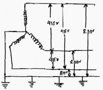
Figure on left shows the multi-grounded neutral systems commonly used by the electric utilities in North America. The neutral grounding reactor is used by some utilities to reduce the available ground fault current while at the same time still maintaining an effectively grounded system.
The multiple earthed neutral (MEN) system of earthing is one in which the low voltage neutral conductor is used as the low resistance return path for fault currents and where its potential rise is kept low by having it connected to earth at a number of locations along its length. The neutral conductor is connected to earth at the distribution transformer, at each consumer’s installation and at specified poles or underground pillars. The resistance between the neutral conductor of the distribution system and the earth must not exceed 10 ohms at any location.
NEC Article 250 Part X Grounding of Systems and Circuits 1 kV and Over (High Voltage)
- Multiple Grounding: The neutral of a solidly grounded neutral system shall be permitted to be grounded at more than one point.
- Multi-grounded Neutral Conductor: Ground each transformer, Ground at 400 m intervals or less, Ground shielded cables where exposed to personnel contact.
Single Grounded Neutral

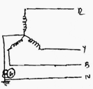
Figure on left shows single grounded neutral which is different from multi grounded system. Figure shows the neutral also connected to earth, but the neutral conductor is extended along with the phase conductors. The configuration shown in figure allows electrical loads, transformers to be placed between any of the three phase conductors, phase-to-phase and/or phase-to-neutral.
This connection, phase to neutral will force electric current to flow over the neutral back to the transformer. So far, this electrical connection is acceptable, as long as the neutral is insulated or treated as being potentially energized, but modifications will be made in the future that will negate safety for the public and animals.
The ground connection would typically be located in the distribution substation. This may appear insignificant, but the differences are significant
Advantages of Multiple grounded neutral Systems
(1) Optimize the Size of Surge Arrestor:
- Surge arresters are applied to a power system based on the line-to-ground voltage under normal condition and abnormal conditions. Under ground-fault conditions, the line-to-ground voltage can increase up to 1.73 per unit on the two, unfaulted.
- Application of surge arresters on a power system is dependent on the effectiveness of the system grounding. The over voltage condition that can occur during a ground fault can be minimized by keeping the zero sequence impedance low. Therefore, optimization in sizing the surge arresters on the system is dependent on the system grounding.
- An effectively grounded power system allows the use of a lower rated surge arrester. The lower rated surge arrester provides better surge protection at a lower cost. An effectively grounded system can only be accomplished using a properly sized, multi-grounded system neutral.
- With Single Grounded Neutral System require the use of full line-to-line voltage rated arresters. This increases the cost of the surge arresters while at the same time reduces the protection provided by the surge arrester. In addition, if the fourth wire neutral is not multi grounded, it would be good practice to place surge arresters at appropriate locations on that conductor.
(2) The zero sequence impedance is lower for a multi grounded system than the single point grounded neutral system.
(3) Freezing and arctic conditions have an adverse impact on the zero sequence impedance. A multi-grounded system neutral will still lower the zero sequence impedance over a single point ground. In fact, without the multi-grounded system, it is more probable that insufficient fault current will flow to properly operate the ground fault protection.
(4) Cost of Equipment for the multi-grounded system is lower.
(5) Safety Concerns on Cable Shields.
- Medium voltage and high voltage cables typically have cable shields (NEC requirement above 5 kV) that need to be grounded. There are several reasons for this shield:
- To confine electric fields within the cable
- To obtain uniform radial distribution of the electric field
- To protect against induced voltages
- To reduce the hazard of shock
If the shield is not grounded, the shock hazard can be increased. With the shield grounded at one point, induced voltage on the shield can be significant and create a shock hazard. Therefore, it is common practice to apply multiple grounds on the shield to keep the voltage limited to 25 volts.
This practice of multi grounding cable shields includes the grounding of concentric neutrals on power cables thereby extending the need for multi grounding of neutrals on the power system.
Disadvantages of Multiple neutral grounding
(1) Less Electrical Safety in Public and Private Property.
- With a multi grounded neutral distribution system it is necessary to have an electrical connection to earth at least 4 times per mile to keep the voltage on the multi grounded neutral from exceeding approximately 25 volts making it safe for the linemen should they come into contact with the neutral and the earth.
- As per NESC Rule 096 C in the section with the multi grounded neutral conductor connected to earth at least 4 times per mile and at each transformer and lightning arrester there are now multiple paths over and through the earth that the hazardous electric current can flow over continuously, uncontrolled.
- The path that this current flow takes through the earth cannot be determined. We cannot put an isotope on each electron and trace its path as it flows uncontrolled through the earth. It is irresponsible to permit stray uncontrolled electric current to flow into and over private property.
- The National Electrical Code (NEC) requires the neutral in the service disconnect and over current panel board to be connected to the earth also. Now the secondary neutral is connected to earth a second time. A parallel connection of the neutral to earth now exists permitting hazardous electric current to flow continuously uncontrolled over the earth.
(2) Earth Fault Protection Relay setting is complicated.
Advantages of Single Grounded Neutral System
(1) More Reliable and Safe System.
(2) Protection Relay Setting is more easy in Single Grounded Neutral:
- Protective relays need to sense abnormal conditions, especially those involving a ground fault. The single point grounded system, with or without a neutral conductor, current flowing into the ground should be considered abnormal (excluding normal charging current). For sensing of ground faults are:

Ground fault relay at neutral
- A current transformer in the location where the neutral is grounded can be used to sense the ground fault (zero sequence) current.
- A zero sequence CT enclosing the three phase and neutral conductors.

CT residual circuit
- Four CT residue circuit (Three CT residual with neutral CT cancellation).
- Protecting against ground faults on a multi-grounded neutral system is more difficult than the single point grounded system since both neutral and ground fault currents must be considered.
- Neutral current and likewise ground fault current can flow in both the neutral and the ground. So, We have must calculate both current as the amount of neutral current which may flow in the circuit, and the ground fault setting must be above this neutral current. This is self explanatory from Fig.
(3) Sensing of Ground Fault current:
- While the sensing of the ground fault current in the single point grounded system is less complex than the multi grounded system, the amount of ground fault current on the single-point grounded system may be greatly limited due to the fact that all ground fault current must return through the earth. This is especially true where the earth resistivity is high, the soil is frozen or the soil is extremely dry.
- John P. Nelson Fellow, IEEE ANSI/IEEE Std 142-1991
- Westinghouse Electric Corporation, Electrical Transmission and Distribution Reference Book NFPA 70
- Jeffery Leib, Train-Car Crashes on the Rise,Denver Post Newspaper, November 7, 2002
- R.T. Beck and Luke Yu, Design Considerations for Grounding Systems






One phase is taken from Transformer and connections at 20 locations given without neutral by providing earth in each house. What will happen in this situation please. The such connections have been given to my villagers
Dear Sir
just i want to ask if the stray current in multi ground neutral can lead to a corrosion in the steel pipes and metal of the building? and if it causes risky step voltage ?
Dear Sir,
I am from cable manufacturing site, Cable of 33KV – 1C x 1000 Sq mm – A2XWaY, (CCV – Line) supplied to customer with all routine test including PD (42 KV) at manufacturing end. After installation cable got failed (after 3 months- 110 Mtr) at end termination point. Electrical expert says that they are providing earth at transformer point only, and not 2 nd. side of cable, they do only neutral connections at 2 nd end, If 2 nd side of armour + shield not earthed, may cause of PD level high and end kit may caused failure, because of 85 mm low creepage, Electrical contractor Started blaming on cable manufacturing side, as they provide guaranteed terminating kit from outside. ,.
Please let me suggest 1. Whether they missed stress cone within jointing kit, 2, They do not have earthed shielded part at 2 nd end. 3. Lack of work while making joint.at 2 nd end, caused high PD and end kit failed.
I asked to their Electrical expert for making shielded connection to earth, they replied that they never make earth at 2 nd points for 3 ph, as they provide neutral at transformer end.
Please suggest whether earth is required at 2 nd side or not. If not what about PD at sending end termination point, electrical expert is giving suggestions to Industries is wrong/right..
Dear sir
in 11kv generators the neutral point is connected to earth via earth coil while in the 33 / 11 kv transformer the neutral point is connected via earth resistor why ?
I think that the problem of system neutral to earth it´s the posibility of some receptor unit domestic or industrial are better grounded than the same source of energy. That case generates recirculation of wanderer currents with difficult localization and harmful impacts. For example, in DC lines railways the ground of the infrastructure system is better grounded in your confluence near a river, with metallic bridge, over concrete pillars with iron soul and immersing in river water earthed power plant. The substation supply that has a large pike and mesh but isn´t sufficient for avoid the ripple current 50Hz above the direct current.
Dear sir please tell me basic difference between clean earth and power earth and pls tell if both are different then i see they are connected in several plant . is this acceptable practic