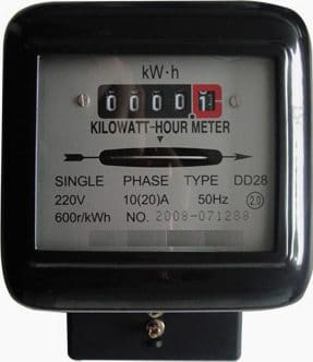
Single phase induction type energy meter is also popularly known as watt-hour meter. This name is given to it. This article is only focused about its constructional features and its working. Induction type energy meter essentially consists of following components:
1. Driving system
2. Moving system
3. Braking system and
4. Registering system
Driving system
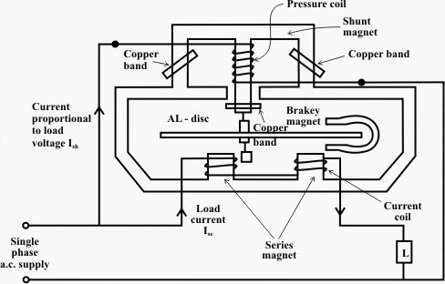
It consists of two electromagnets, called “shunt” magnet and “series” magnet, of laminated construction. A coil having large number of turns of fine wire is wound on the middle limb of the shunt magnet.
This coil is known as “pressure or voltage” coil and is connected across the supply mains. This voltage coil has many turns and is arranged to be as highly inductive as possible. In other words, the voltage coil produces a high ratio of inductance to resistance.
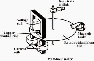
An adjustable copper shading rings are provided on the central limb of the shunt magnet to make the phase angle displacement between magnetic field set up by shunt magnet and supply voltage is approximately 90 degree.
The copper shading bands are also called the power factor compensator or compensating loop. The series electromagnet is energized by a coil, known as “current” coil which is connected in series with the load so that it carry the load current. The flux produced by this magnet is proportional to, and in phase with the load current.
Moving system
The moving system essentially consists of a light rotating aluminium disk mounted on a vertical spindle or shaft. The shaft that supports the aluminium disk is connected by a gear arrangement to the clock mechanism on the front of the meter to provide information that consumed energy by the load.
The time varying (sinusoidal) fluxes produced by shunt and series magnet induce eddy currents in the aluminium disc.
The number of rotations of the disk is therefore proportional to the energy consumed by the load in a certain time interval and is commonly measured in kilowatt-hours (Kwh).
Braking system
Damping of the disk is provided by a small permanent magnet, located diametrically opposite to the a.c magnets. The disk passes between the magnet gaps. The movement of rotating disc through the magnetic field crossing the air gap sets up eddy currents in the disc that reacts with the magnetic field and exerts a braking torque.
By changing the position of the brake magnet or diverting some of the flux there form, the speed of the rotating disc can be controlled.
Registering or Counting system
The registering or counting system essentially consists of gear train, driven either by worm or pinion gear on the disc shaft, which turns pointers that indicate on dials the number of times the disc has turned.
The energy meter thus determines and adds together or integrates all the instantaneous power values so that total energy used over a period is thus known.
Working of Single phase induction type Energy Meter
The basic working of Single phase induction type Energy Meter is only focused on two mechanisms:
- Mechanism of rotation of an aluminum disc which is made to rotate at a speed proportional to the power.
- Mechanism of counting and displaying the amount of energy transferred.
Lets have a look over these mechanism in few words:
Mechanism of rotation of an aluminum disc
Which is made to rotate at a speed proportional to the power.
The metallic disc is acted upon by two coils. One coil is connected 0r arranged in such a way that it produces a magnetic flux in proportion to the voltage and the other produces a magnetic flux in proportion to the current. The field of the voltage coil is delayed by 90 degrees using a lag coil.
A permanent magnet exerts an opposing force proportional to the speed of rotation of the disc – this acts as a brake which causes the disc to stop spinning when power stops being drawn rather than allowing it to spin faster and faster. This causes the disc to rotate at a speed proportional to the power being used.
Mechanism of displaying the amount of energy transferred
Based on number of rotation of aluminum disc.
The aluminum disc is supported by a spindle which has a worm gear which drives the register. The register is a series of dials which record the amount of energy used.
The dials may be of the cyclometer type, an odometer-like display that is easy to read where for each dial a single digit is shown through a window in the face of the meter, or of the pointer type where a pointer indicates each digit.
It should be noted that with the dial pointer type, adjacent pointers generally rotate in opposite directions due to the gearing mechanism.





Induction type energy meter disc which shape
If the permanent magnet move towards the aluminium disc the speed of disc will increase or decrease . Why?
Single phase induction type energy metre
Answering this question may lead bad influence to the electrical community! 🤔
Good morning everyone, if you connected three energy kWh meters class 2 on a say consuming circuit that will run maybe 21 days, what is the expected kWh readings between each one of them.
on the energy meter above, what is the meaning of 600r/kwh
Meaning for 600r/kwh. If energy meter rotating in 600 rotations, there was consumed 1 kwh(1 unit).
what will be the performance where there are many different power factor load(linear non linear)?
A kWh meter is specifically designed to read only “real” energy and is unaffected by capacitance or inductance of the system. It is also theoretically unaffected by non linearity.
About
Single phase dynamometer type energy meter
What will happen if the current direction reverses in energy meter?
Is it possible that meter starts rotating in reverse direction?
The answer to your question is yes. In a typical residential, single phase meter (Form 2S type) the upper two lugs are connected to utility source and lower lugs are connected to the house branch circuit panel. If the meter is inserted in the socket upside down, it will in fact rotate backward and subtract apparent energy usage from the register. Meters can be purchased with what is referred to as a “detent” which is a ratchet that does not allow a meter to turn backward. If installed upside down, a meter with a detent will simply not turn at all.
is there any difference between how the kwh hour usage is calculated compared to the newer watt hour meter. sse are telling me my meter is read as 1 unit = 1kwh. / But my meter says it has a kh factor of 3..0 . not 1.0kh. is there a difference between the 2
Why is electromagnetic induction technology mostly used in energy meters?
Electromagnetic, or perhaps electromechanical meters, were invented by Shallenberger, a Westinghouse electrician in the 1890’s and it was almost identical to such meters in modern usage. Prior to that, an electrochemical technique using electrolytic cells were sometimes used that required weighing the migration of a metal, such as zinc or mercury, from anode to cathode. Another method used Kelvin heating but I am not sure how this worked. These techniques were purported to be labor intensive as well as inaccurate. Modern, Shallenberger type meters are extremely accurate if applied correctly. Most electric utilities are phasing out electromechanical meters in favor of electronic meters which I don’t think improve accuracy, but have lower maintenance.
nice
From the specification shown on the energy meter above, what is the meaning of 10(20)A ,please?
10 Amp is the nominal rating of the meter. 20 Amp the maximum rating within the accuracy class of the meter.
10A is the rated current and 20A is the highest current when the energy meter works accurately.
This is a non-North American meter since it is 50 Hz. I am from the U.S. so I am unfamiliar with this meter face labeling, but I think that this is what is referred to as the metering class or current rating of the meter. Assuming this the case, this meter is rated for nominally 10 amperes, or a maximum of 20 amperes for rated metering accuracy. If I have this correct, in the U.S., this meter is referred to as a “transformer rated” meter, meaning that it is designed to meter large services, in excess of 200 amperes. Current transformers are required in the main service wires, to scale the large current down to much lower current value, nominally 5 amperes. The energy consumption, as displayed by the meter register, is multiplied by the primary/secondary current ratio of current transformers to determine actual kWh consumption.
With the meter disconnected, I’m getting a resistance of 600 ohms across the load side of the meter. Is this right?
me to, I get 570 ohms. it must be the coils? seems like it would be a lot of power used,
great…
great explaination!I have read about this topic till now.
I am looking to design an eddy current drive for a truck wheel that is still mounted on its hub or axle and suspended in air as in a situation to change the tire. The idea is simple. Make a “U”/shoe shaped magnet made out of laminations, provide shaded poles AC to reach the “Rim” which is either steel or aluminum that should act as the disc. The supply voltage is 115 single phase; or 200V, 3 phase.