
Project saviour details
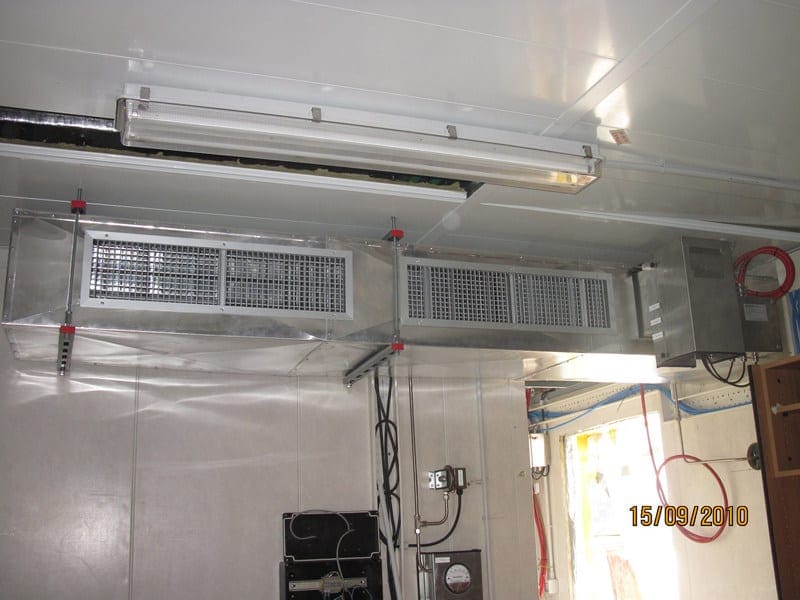
To be honest with you, the planning and installation of LV switchgear is a damn complicated job. But you knew that :) There are dozen of detail where you can stumble, if not planned carefully as they should be. The later installation phase (and not to speak about commissioning phase) largely depends on the in-detail planned first phase, which usually includes the organization of transportation, design of switchgear room and clearances, various civil works, safety against arcing faults, and so on.
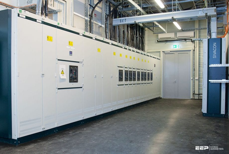 Planning and installation of low voltage switchgear - The devil is in the detail! (photo credit: evotech.hu)
An old saying “The devil is in the detail” actually perfectly fits here. This technical article will try to shed some light on some tricky details which can be in some situations a project saviour.
Like medium-voltage switchgear, low-voltage switchgear is also less often installed with individual panel design on site, but delivered as factory-assembled, type-tested switchgear. For design verification, testing is to be accomplished successfully in compliance with IEC 61439-1 and IEC 61439-2.
- Installation (clearances and corridor widths)
- Important planing considerations
- Transportation switchgear units
- Double-front installations
- Environmental conditions for switchgear
- Safety against arcing faults
- Other important things you should be aware
1. Installation (clearances and corridor widths)
The minimum clearances between switchgear and obstacles specified by the manufacturer must be taken into account when installing low-voltage switchgear (Figure 1). The minimum dimensions for operating and servicing corridors in accordance with IEC 60364-7-729 must be taken into account when planning the space requirements (Figure 1, Figure 3).
Where:
- Minimum height of passage under covers or enclosures.
- Attention: Above the panels, some space specified by the manufacturer MUST be free from obstacles to allow the pressure relief vents to open in the event of an arcing fault.
Where:
- With switchgear fronts facing each other, the space requirements only account for obstruction by open doors from one side (i.e. doors that don’t close in escape direction).
- Take door widths into account, i.e. door can be opened at 90° minimum.
2. Important planing considerations
The following aspects should be considered in particular when planning low-voltage main distribution system:
Point № 1 – Maximum permissible panel equipment (for example, number of LV HRC in-line switch-disconnectors taking into account the disconnector size and load; the manufacturer specifications must be observed!)
Point № 2 – Minimum panel width taking into account the component density, cable connection cross sections and number of cables (possibly a wider terminal compartment needs to be selected or an additional panel be planned)
Point № 3 – The reduction factors of the devices according to the manufacturer specifications must be observed! Here, the mounting location, ambient temperature, and rated current play an important part.
This is particularly important for currents greater than 2,000 A!
Point № 4 – The dimensioning of compensation system largely depends on the installation site (office, production, etc.) and network conditions (harmonic content, distribution system operator specifications, audio frequency, etc.). As a rough estimate, approximately 30% (in the industry) of the transformer power can be expected if there are no concrete planning specifications.
Point № 5 – The decision between central or distributed compensation (see chapter 5) depends on the network topology (centre of the reactive current originators).
In the case of a distributed arrangement of the compensation systems, appropriate outgoing feeders (low voltage HRC in-line switch-disconnectors, circuit-breakers, etc.) are to be provided in the low-voltage main distribution system.
Point № 6 – Generator-fed networks must not be compensated if a regulated compensation could lead to problems in the generator control (deactivate compensation upon switching to generator mode or use fixed compensation matched to the generator is possible).
Point № 7 – Choking of a compensation system depends on the requirements of the network, the customer, and also the distribution system operator.
Further reading:
How to determine compensation of reactive power of an electrical installation
3. Transportation switchgear units
Depending on the access routes available in the building, one or more cubicles (or columns) can be combined into transportation units. The maximum length of a transporation unit should not exceed 2,400 mm. The panel weights are to be used for the transportation and dimensioning of building structures such as cable basements and false floors.
Attention! If a lift truck is used to insert circuit-breakers or withdrawable units, the minimum corridor widths must be adapted to the lift truck!
Lifting with a crane is the preferred method of handling (see Figure 4), however, overhead obstructions or low ceilings often dictate the method to be used.
Moving switchgear in an obstructed area where a crane cannot be employed can be accomplished by the use of rollers (for indoor enclosure only).
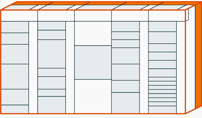
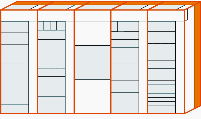
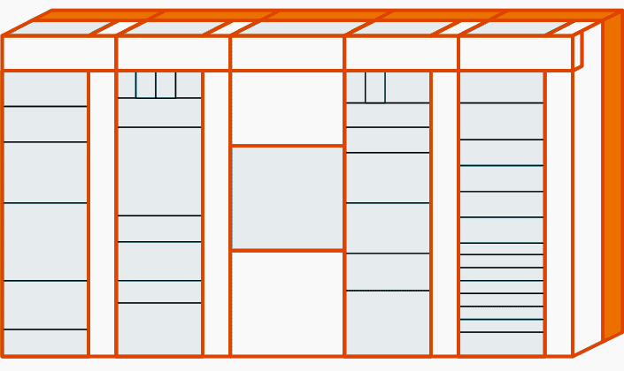
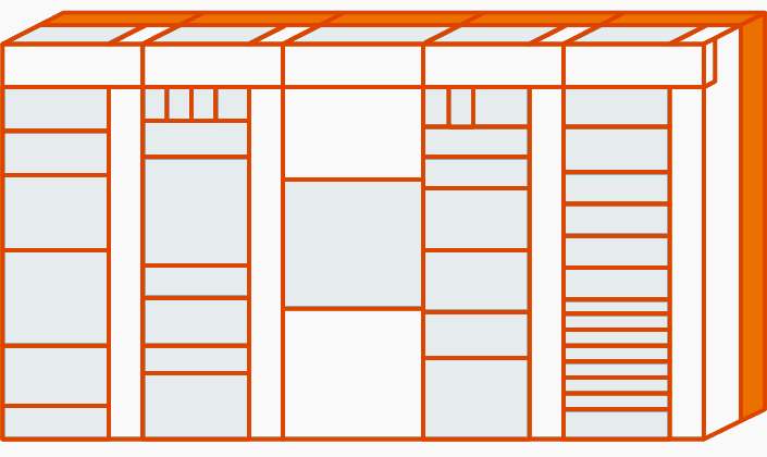
4. Double-front installations
In a double-front installation, the cubicles are positioned in a row next to and behind one another. The main feature of a double-front installation is its extremely economic design, since the branch circuits on both operating cubicles are supplied by one main busbar system only.
The “double-front unit” structure is required for the assignment of certain modules.
A double-front unit in Figure 5 consists of a minimum of two and a maximum of four cubicles. The width of the double-front unit is determined by the widest panel (1) within the double-front unit. This cubicle can be placed on the front or rear side of the double-front unit. Up to three more cubicles (2), (3), (4) can be placed on the opposite side. The sum of the cubicle widths (2) to (4) must be equal to the width of the widest cubicle (1).
The panel combination within the double-front unit is possible for all technical installations with some exceptions explained below.
Exceptions!
The following cubicles determine the width of the double-front unit and may only be combined with an empty panel:
- Busbar coupler, longitudinal (BCL)
- 5,000 A incoming/ outgoing feeder
- 6,300 A incoming/ outgoing feeder
5. Environmental conditions for switchgear
The climate and other external conditions (natural foreign substances, chemically active pollutants, small animals) may affect the switchgear to a varying extent. Their effect depends on the heating and air-conditioning systems of the switchgear room.
If higher pollutant concentrations are present, reducing measures are required, for example:
- Air-intake for the operating room from a less contaminated point
- Slightly pressurizing the operating room (e.g. by blowing uncontaminated air into the switchgear)
- Switchgear room air conditioning (temperature reduction, relative humidity < 60 %, use of air filters, if necessary)
- Reduction of the temperature rise (oversizing of switchgear or components such as busbars and distribution bars)
6. Safety against arcing faults
As for transformers and medium-voltage switchgear, an arcing fault occurring in the low-voltage switchgear can lead to dangerous interferences with serious consequences and damage neighbouring outgoing feeders, panels or even the entire installation.
Arcing faults may arise from wrong dimensioning, insulation deterioration such as pollution, but also from handling faults. High pressure and extremely high temperatures can have fatal consequences for the operator and installation, these consequences may even extend to the entire building.
The testing of low-voltage switchgear under arcing fault conditions is a special test in compliance with IEC TR 61641.
Active protective measures – Measures such as high-quality insulation of live parts (for example, busbars), uniform and easy handling, integrated operator fault protection, and correct switchgear dimensioning prevent arcing faults and hence personal injuries.
Passive protective measures – They increase operator and installation safety many times over. They include arcing-fault-proof hinge and lock systems, safe handling of withdrawable units or circuit-breakers only when the door is closed, and flap traps behind front air vents, arc barriers or an arcing fault detection system in combination with a fast interruption of arcing faults.
The arcing fault levels (Figure 7) describe the classification according to the properties under arcing fault conditions and the limitation of the effects of an arcing fault on the installation or parts thereof.
Arcing fault level 1
High degree of personal safety without extensive limitation of the arcing fault effects within the installation.
Arcing fault level 2
High degree of personal safety with extensive limitation of the arcing fault effects to one panel or double-front unit.
Arcing fault level 3
High degree of personal safety with limitation to the main busbar compartment on a panel or double-front unit and the device or cable connection compartment.
Arcing fault level 4
High degree of personal safety with limitation of the arcing fault effects to the place of origin.
6.1 Reducing the occurrence probability of an arcing fault
In the intensive discussion about arcing fault detection or interruption, technically elaborate and expensive solutions are readily propagated. Some manufacturers like Siemens, however, has for a long time preferred the prevention of arcing faults by means of complete insulation of all conductive parts inside the installation (busbars, connections, transfers, etc.).
Such passive precautions ensure that no arc is generated that would have to be detected and quenched. See Figure 11.
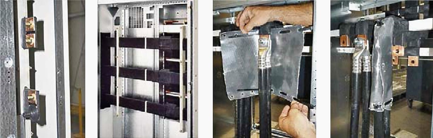
Active systems for the detection and interruption of an accidental arc as a consequence of a fault need maintenance and do not provide any advantages with regard to the installation availability. The impacts of an arcing fault (pollution, metal splashes, etc.) might be minor, but they usually have to be cleared nevertheless.
Moreover, the interruption device of the active system has to be replaced. This work can be laborious and time-consuming.
Monitoring of the outgoing feeder areas of the switchgear is not recommended for active systems for reasons of reliability of supply, as arcing faults in these areas should be interrupted by the upstream protective device. Otherwise, such a fault would lead to a complete shutdown of the installation.
For feed-in monitoring (terminal compartment), the system must act on the upstream protective device. Thus, the advantage of a fast interruption by the active system is lost in the case of such a fault.
7. Other important things you should be aware
The following aspects are particularly important for the configuration of low voltage switchgear:
7.1 Environmental and installation conditions, mechanical stress
- Degree of protection in acc. with EN 60529 protection against contact, dust and water protection
- Ambient temperature and climatic conditions
- Corrosion
- Type of installation and fastening (for example, stand-alone, on the wall)
- Cover or doors (as appropriate transparent or nontransparent)
- Dimensions, weight:
- Maximum permissible outer dimensions of the switchgear
- Maximum permissible dimensions and weight of the switchgear for transport and erection at the site of installation
- Cable duct (base panelling, if required)
- Cable glands
- Type of cable laying (cable duct, cable racks, etc.)
- Device installation (fixed or plug-in /withdrawable units for quick replacement)
- Accessibility of devices:
Parts that can be operated during operation (such as fuses or miniature circuit-breakers) are to be combined and arranged within the switchgear assembly in such a way that they are separately accessible (via a quick-release cover, for example). Contactors and fuses are to be placed in separate boxes.
Recommended technical article related to this subject:
Good Practice Rules For In-Process Inspection Of Low Voltage Switchboard
7.2 Type of installation, accessibility
To ensure that the most economical design can always be selected, the main features of low voltage switchgear should be weighed against each other and a decision be made before defining the structural measures.
Such features are:
- Open or closed design (kind of operating site)
- Self-supporting installation: stand-alone in the room, at a wall or in a wall recess
- Not self-supporting installation: for mounting to the wall, to a supporting frame or in a wall recess
- Kind of accessibility for installation, maintenance, and operation
- Dimensions (installation height, depth, width)
- Notes regarding structural measures
Further reading on this subject:
7.3 Selection of the electrical equipment
The following has to be considered for the equipment to be installed in switchgear assemblies:
- The applicable device specifications
- The suitability with regard to nominal data, in particular short-circuit strength and breaking capacity
- The installation of current-limiting protective equipment might be necessary
Further reading on this subject:
Five switching devices you are likely to spot in most of the low voltage switchgear
7.4 Protective measures
- Protection against direct contact in the distribution board when the door is open by means of contact protection covers, degree of protection IP30
- Protection against indirect contact at all frame and cladding parts by means of Safety class I (protective conductor connection) and Safety class II (protective insulation).
More information about protection against indirect contact:
Guide To Protection Against Indirect Contact And Earth Fault
7.5 Space requirements for built-in units, busbars and terminals
When configuring built-in components in encapsulated switchgear and distribution switchboards, sufficient space must be provided beyond the pure space requirements of the units for:
- The electrical clearance (clearance in air) to the encapsulation
- The heat dissipation of the individual units
- A possibly required blow-out room in switching devices
- The wiring
- The connection of external incoming and outgoing feeder cables (terminal compartment)
- The device identification
Meters and measuring instruments should be located at eye level. All devices that are to be operated manually should be within reach (approximately at a height between 0.6 and 1.8 m). Restrictions resulting from the use of a device in an encapsulation might have to be observed, for example, with regard to the rated current and the switching capacity.
Sources: Siemens (Planning guide for electrical power distribution, Receiving, handling and storage), GE (Installation of electrical switchgears)
Related electrical guides & articles


Edvard Csanyi
Hi, I'm an electrical engineer, programmer and founder of EEP - Electrical Engineering Portal. I worked twelve years at Schneider Electric in the position of technical support for low- and medium-voltage projects and the design of busbar trunking systems.I'm highly specialized in the design of LV/MV switchgear and low-voltage, high-power busbar trunking (<6300A) in substations, commercial buildings and industry facilities. I'm also a professional in AutoCAD programming.
Profile: Edvard Csanyi

please any one guide me, as per standard how much time required for a single medium voltage panel installation, testing and commissioning. thanks.
Oh yeah, the details are ever forgotten. details like UPS system to feed command and protection or how small is civil design of electric room. Sometimes i think that designers are thinking that the room will only have a desk an 4 chairs…
Sir I would like to ask you , 500 meter
Distance and capacity 800 Amp so how much size of cable will be use in low voltage …?which type cable can be use?
Please reply me
Hi, I believe that is too much power for 500meters of lengh circuit… I will use MV system in this case
Información bien realizada y aplicable al comissionamiento
This article is very interesting. I will get some ideas.