
The effects of low power factor
Why are power engineers interested in plant power factor, what causes low power factor, and how can it be improved? The objectives of this article are to answer these questions briefly and to include handy application information for power-factor problems. The effects of low plant operating power factor could be very bad.
 Why should plant engineers be worried about the power factor? What’s the catch?
In summary, the effects of low plant operating power factor may be any or all of the following: overloaded cables, transformers, etc.; increased copper losses; reduced voltage level, resulting in sluggish motor operation; reduced illumination from lighting, especially where an old incandescent lamps are used; and increased power costs where a power-factor clause, or its equivalent, is part of the rate structure and is enforced.
Generally, low power factor could be due to partially loaded induction motors. Frequently drives are “overmotored,” i.e., the motor is selected to handle the largest load but usually operated at less than full load.
There are also other factors contributing to lower power factor, such as replacement of incandescent lamps with fluorescent lamps; use of rectifiers instead of synchronous motor-generator sets for DC power supply; and increased installation of various induction devices, electronic equipment, air-conditioning units, etc.
As plants become more and more complex it can be expected that the plant power factor will become poorer unless some corrective measures are taken. Improvement of power factor can reduce power costs, release electrical capacity of the power distribution system, raise the voltage level, and reduce the system losses.
However, the two main reasons for improving the power factor are:
- To reduce the power bill when there is a power factor incentive in the rate clause and
- To increase or release electrical capacity of the power distribution system.
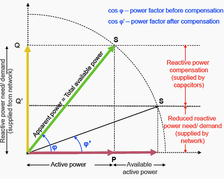
Although the first (to reduce the power bill) is still of primary importance, the second is becoming more important as engineers recognize the economics. This is especially true when capacitors are used for power-factor improvement because the electrical capacity released is valued at several times the cost of capacitors.
The two most common methods for improving power factor are shunt capacitors or synchronous motors. Each has its own application. Usually the capacitor method is most economical and practical for existing plants, while the synchronous motor finds its main application when a new and large motor drive is added.
Power factor fundamentals
The usual definition of power factor in terms of the phase relationship of voltage and current in a sine wave is intentionally avoided because it is abstract and difficult to translate into a simple physical concept. The concept used here is based on the fact that there are two types of current in an AC circuit is particularly helpful in understanding the effect of power factor on system operation and understanding capacitor applications.
Although the following discussion on fundamentals is written around the use of capacitors because they generally are the most practical and economical means for improving the power factor, these fundamentals also apply to other methods, such as synchronous motors and condensers.
Power-producing current (or working current) is that current which is converted by the equipment into useful work such as turning a lathe, making a weld, or pumping water. The unit of measurement of the power produced is t,he kilowatt (kw).
Magnetizing current (also known as wattless, reactive, or non-working current) is that current which is required to produce the flux necessary to
the operation of induction devices. Without magnetizing current, energy could not flow through the core of a transformer or across the air gap of an induction motor.
The unit of measurement of magrietizing volt-amperes is the kilovar (kvar).
Total current is the current that is read on an ammeter in the circuit. It is generally made up of both magnetizing current and power-producing current. The unit of measurement of total volt-amperes or “apparent power” is the kilovolt-ampere (kva). Most a-c power systems require both kilowatts and kilovars.
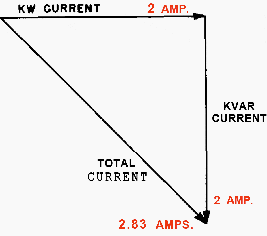
2 + 2 Does Not Equal 4!
The arithmetic applicable to everyday life follows the simple rule that 2 + 2 = 4. It is unfortunate that instead of following such a simple rule the addition of kilovar current and kilowatt current follows a principle of geometry.
If the kilowatt and kilovar components of current are each 2 amp, Figure 2, the total current may be found from the right-triangle relationship as follows:
- (kilovar current)2+ (kilowatt current)2 = (total current)2
- 22 + 22 = (total current)2
- 4 + 4 = (total current)2
The following useful formulas apply when kw, kvar, and kva are substituted for their respective currents:
- kva = √( (kw)2 + (kvar)2 )
- kw = √( (kva)2 – (kvar)2 )
- kvar = √( (kva)2 – (kw)2 )
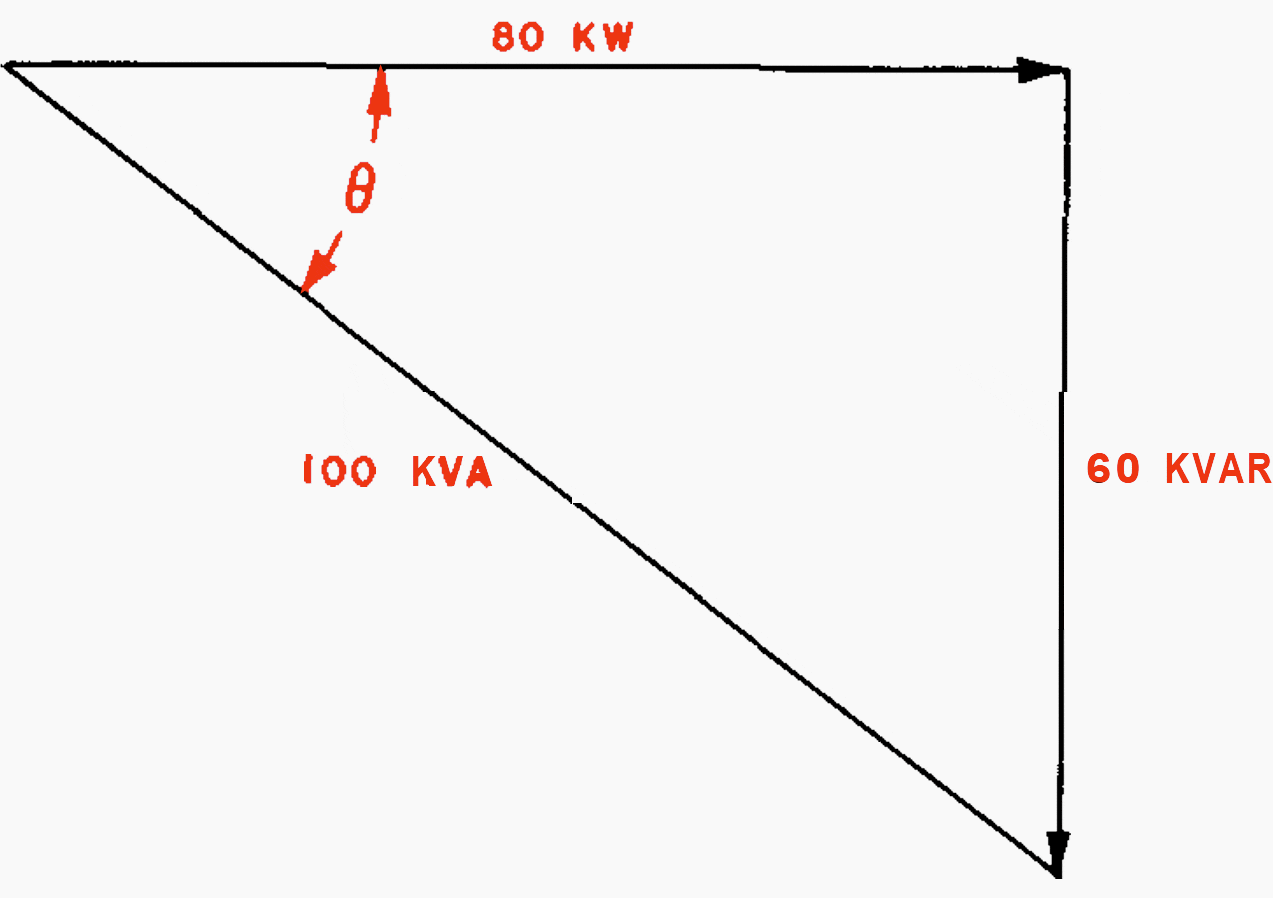
What is power factor?
Power factor may be expressed as the ratio of power-producing current in a circuit to the total current in that circuit. Another definition of power factor, which is generally more useful, is the ratio of kw or working power to the total kva or apparent power.
Thus,
- Power factor = kw / kva
- kw = kva × pf
- kva = kw / pf
For the case illustrated in Figure 3 the power factor is 80/100, or 0.8, or, as it is commonly expressed, 80 per cent. The angle included between the kva and the kilowatt components is called the power-factor angle and is designated by the symbol θ.
The cosine of this angle (cox θ) is the power factor.
The actual calculation of power factor is illustrated by the following example.
[to]
Example 1
What is the power factor of the load on a 460-volt three-phase system if the ammeter indicates 100 amp and the wattmeter reads 62 kw?
Since in a three-phase circuit:
- kva = (√3 × amperes) / 1000
- kva = (1.73 × 460 × 100) / 1000
- kva = 79.6
Power factor = kw/kva = 62/79.6 = 0.78, or, as it is often expressed, 78 per cent.
Leading and lagging power factor
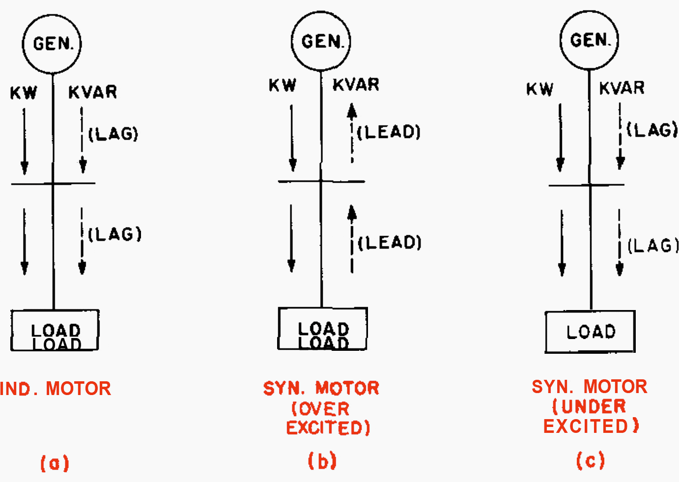
The terms leading and lagging power factor are apt to be confusing, and they are meaningless unless the direction of both kilowatt and kilovar flow is known. Generally, however, in industrial plants only the load power factor is considered, in which case the following rule may be helpful in differentiating between leading and lagging power factor:
On the other hand, an overexcited synchronous motor can supply kilovars (from the motor DC field action), so such a synchronous motor has a leading power factor.
Table 1 and associated Figure 4 indicate the power factor for common operating conditions for both loads and supply sources based on the direction of kilowatt and kilovar flow.
Table 1 – Power Factor of Load and Source
| Fig. | Type of load | At load | At generator | ||||
| Kw | Kvar | Power factor (1) | Kw | Kvar | Power factor (2) | ||
| a | Induction | In | In | Lag | Out | Out | Lag |
| b | Synchronous motor (overexcited) | In | Out | Lead | Out | In | Lead |
| c | Synchronous motor (undrexcited) | In | In | Lag | Out | Out | Lag |
(1) Power factor measured at the load.
(2) Power factor measured at the generator
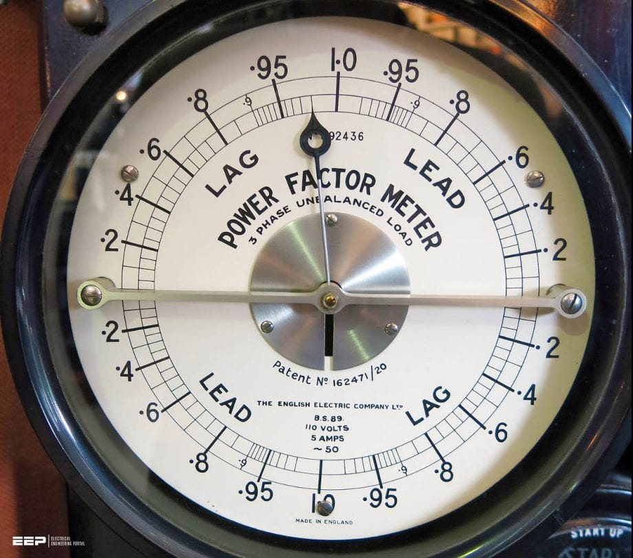
It is obvious from this table that the terms leading and lagging are apt to be confusing. In order to avoid this confusion, varmeters are replacing power-factor meters.
The varmeter has a zero center point with scales on either side, one labeled “in” and the other “out.”
In most industrial circuits the kilowatt flow is in only one direction, e.g., to a motor load; so single-scale wattmeters are customarily used. However, in a tie line or transfer circuit a wattmeter with a center point should be used.
Kilovar readings are generally more useful than power-factor readings as they indicate the actual magnitude of the magnetizing components.
Further reading:
How To Control Reactive Power In Larger Electrical Plants With Multiple Incomers
Source: Industrial Power Systems Handbook by Donald Beeman
Related electrical guides & articles


Edvard Csanyi
Hi, I'm an electrical engineer, programmer and founder of EEP - Electrical Engineering Portal. I worked twelve years at Schneider Electric in the position of technical support for low- and medium-voltage projects and the design of busbar trunking systems.I'm highly specialized in the design of LV/MV switchgear and low-voltage, high-power busbar trunking (<6300A) in substations, commercial buildings and industry facilities. I'm also a professional in AutoCAD programming.
Profile: Edvard Csanyi

thank you Edvard for the excellent demonstration of the power factor, PF is very important especially in gaz turbin based power plant where the efficiency is beyond 45%(huge west of money) , and I hope the next topic would be about the distorted power factor (DPF)
I can’t believe I am seeing this, this was basic covered back in my college days, don’t they have the basics anymore? This topic is more important with the influx of solar power. So few comprehend the implications on power electronics.
…. Good Day ! will glad to rcvd some link for practical info about Power Factor . Thanks and BRGDS Igor
My monthly Bill is KWH 188496, KVAH 188804 and KVARH 6460
I always have doubt their is something wrong.
Can you please guide me
am thinking of being a member, thanks.
Hello,
I want to contribute to your awesome website – Can I also submit articles regarding electrical testing and maintenance in substation for reference and understanding of concepts for knowledge seekers ?