
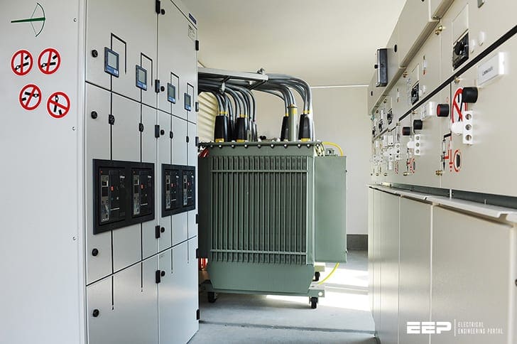
Single-transformer, single-bus configuration
The utility supply voltage depends on both availability and consumer requirements. The consumer transformer is connected delta on the high-voltage side and grounded wye on the low-voltage side. A fused-disconnect switch provides three-phase switching and protection for the transformer, as well as physical isolation of the transformer during maintenance.
 Protection scheme for the substation with a single supply from the utility
The consumer voltage may range from 480 V to 34.5 kV. As stated above, power transformer is connected delta/wye and system configuration is single-transformer / single-bus.
A normally open feeder tie switch is shown to facilitate circuit breaker maintenance.
- Transformer protection
- Transformer low-side bus and feeder protection
- Protection of the supply line
- Selective coordination and transformers (VIDEO)
1. Transformer protection
Several factors are involved in selecting the transformer high-side fuses.
FACTOR #1 – In general, the voltage rating of the fuse should be equal to or greater than the system phase-to-phase voltage. Solid material expulsion-type fuses are not “voltage critical” and may be applied on systems rated less than the voltage rating of the fuse.
This overvoltage typically restricts application of current-limiting fuses to the same system voltage class as the maximum voltage rating of the current-limiting fuse.
FACTOR #2 – The interrupting rating of the fuse should be equal to or greater than the maximum anticipated fault
duty, including possible utility system expansion.
FACTOR #3 – The continuous current rating of the fuse should be equal to or greater than the maximum anticipated emergency loading of the transformer.
IMPORTANT! Overload capability of power fuses may vary from 0% to 40% with different fuse types and with different ampere ratings of the same fuse type.
FACTOR #4 – The continuous current rating and melting time-current characteristics of the fuse should be selected to provide optimum transformer protection as well as coordination with upstream and downstream relays or fuses, taking into account the effect of ambient temperature and load current heating.
If two transformers are involved, as in Figure 2, the fuse size and relay setting or fuse coordination should be selected based on the normal maximum loading level of both transformers.
Coordination with the low-side breaker may be sacrificed under emergency loading conditions with one transformer out of service.
FACTOR #5 – Primary fusing as the only means of transformer protection may not be suitable if the secondary ground fault current is limited by using resistance grounding on the neutral.
If low-resistance grounding is used, several relay schemes can be employed to clear a ground fault between the transformer and feeder breakers, or beyond the feeder breakers if one fails to open.
All of these schemes use a neutral CT and overcurrent relay (51G).
resistance-grounded systems
For a low-resistance-grounded system, the use of an overcurrent relay connected to a CT in the service transformer neutral is usually the best option. This CT should have a ratio smaller than the phase CT’s, and the relay pickup range in conjunction with the neutral CT should allow a pickup as low as 10% of the neutral resistor rating.
When an overcurrent relay is utilized with a zero-sequence CT it is referred to as a 50G, 51G or 50/51G relay depending upon relay type used. Figure 4 shows typical arrangements for both these applications.
This neutral overcurrent relay (51G) trip output can be connected to do one of the following:
- Close a high-side grounding switch to force tripping of the remote utility breaker
- Open a high-side motor-operated switch that is rated to interrupt such faults
- Transfer trip the remote utility breaker
2. Transformer low-side bus and feeder protection
The fuse provides protection for transformer high-side and low-side faults. It also provides limited backup protection for low-side feeder faults.
On short feeders, where the magnitude of fault current does not decrease significantly from the bus to the end of the feeder, coordination of the instantaneous relays with downstream protective devices may be difficult, if not impossible. The time-overcurrent relays should coordinate with the largest protective device on the feeder.
The time current characteristics of the relays should be selected accordingly.
For coordination with branch fuses, a very inverse or extremely inverse-time characteristic should be selected. Phase relay pickup should be greater than the expected full load current on the feeder.
It is also important to check coordination of the time-overcurrent relay with the transformer high-side fuse. Coordination should be reviewed when the load-side tie switch is closed. The phase relay pickup should be high enough to carry the load of both feeders and still provide adequate fault protection while maintaining coordination with the high-side fuse.
Feeder ground fault protection may be provided by non-directional instantaneous and time-overcurrent relays. A ground relay, connected in the neutral circuit, is not sensitive to balanced three-phase load current.
Only currents resulting from an unbalanced load (on a four-wire system), or unbalanced faults involving ground, will flow in the ground relay. Thus, the feeder full load current need not be a directly considered when determining relay pickup.
The following are two different methods for setting ground relays:
- Maximum coordination
- Maximum ground fault sensitivity
a) Maximum coordination
The ground relay has a setting identical to that of the phase relays. This ensures the same degree of coordination with downstream protective devices as the phase relay.
The ground relay will provide redundancy in the event of phase relay failure for a line-to-ground fault.
b) Maximum ground fault sensitivity
The ground relay instantaneous and time-overcurrent pickup may be set much lower than phase relay pickup. This provides sensitive protection for ground faults but may also result in feeder outages for faults that would normally be cleared by downstream protective devices.
For greater sensitivity, the ground relay may also be set with a time-overcurrent relay pickup of about one-half that of the phase relay but with a high time-dial setting to coordinate with downstream fuses over a reasonable range of fault current.
3. Protection of the supply line
Different supply voltage levels generally dictate different levels of utility line protection. These systems will normally trip instantaneously for all line faults. The utility’s instantaneous relaying may reach into the consumer’s transformer, but not completely through it.
Ideally, transformer faults that are detected by instantaneous line relaying should also blow the transformer fuse. This permits the line to be re-energized and the fault located.
Transformer isolation in this manner may not always be possible, particularly on utility systems with large fuses and relatively low levels of ground fault current.
If coordination between the fuses and the supply line protection is not possible, the consumer may be required to use relay protection (connected to high-voltage CTs) for the transformer, instead of fuses.
Failure to achieve coordination may result in nuisance tripping, additional damage to the transformer due to supply line automatic reclosing, and an extended outage of the supply line while maintenance personnel are trying to locate the fault.
4. Selective coordination and transformers (VIDEO)
Part 1
Calculating the required fuse ampacity ratios for selective coordination between the primary side and secondary side of a transformer and downstream circuits.
Part 2
Selectively coordination circuit breakers around a transformer.
Part 3
Achieving selective coordination between fuses and circuit breakers when protecting transformers.
Sources:
- IEEE Std C37.95 – IEEE Guide for Protective Relaying of Utility-Consumer Interconnections
- System Protection by Bill Brown at Square D Engineering Services
Related electrical guides & articles


Edvard Csanyi
Hi, I'm an electrical engineer, programmer and founder of EEP - Electrical Engineering Portal. I worked twelve years at Schneider Electric in the position of technical support for low- and medium-voltage projects and the design of busbar trunking systems.I'm highly specialized in the design of LV/MV switchgear and low-voltage, high-power busbar trunking (<6300A) in substations, commercial buildings and industry facilities. I'm also a professional in AutoCAD programming.
Profile: Edvard Csanyi

I really like it our goal. Your information is very important to me. Thank you so much for your support of the online.
I wonder why the power outtage happen all the time in my native country capital in Ysngon, Myanmar. That why i am interesting reading power related article.