Introduction to protective grounding
This technical article covers protective grounding requirements for steel tower and wood pole supported transmission and distribution lines, and insulated power cables. Protective grounds must be installed so all phases of lines or cable are visibly and effectively bonded together in a multi-phase “short” and connected to ground (earth) at the worksite.

Single-phase grounding of multi-phase circuits is prohibited. Conductive objects within reach of any worker, either aerial or on the ground, should be bonded to this grounding system. Therefore, a sufficient quantity of protective grounds should be installed at the worksite in a manner that places them directly in shunt with all points of contact by workers.
Installation of protective grounds on power line structures creates an equipotential safe work zone on the structure. However, without benefit of installed ground mats, hazardous step, touch, and transferred touch potentials may exist on the ground near structure footings and objects bonded to the worksite grounding system during an accidental energization of the line.
Take a look at the Figure 1 below.


Keep in mind that when ground fault current flows there will be a voltage rise at every connection to earth. No one should approach to within 10 feet of a protective grounded structure or any other conductive object which has been bonded to the worksite grounding system unless protective measures are in place to reduce the hazard of step and touch voltages.
Otherwise, only when necessary to gain access to a structure from the ground, linemen must approach quickly and mount/dismount at the base of the structure.
1. Grounding on Metal Transmission Structures
1.1 Lattice Steel Structures
The preferred method for installing grounds on higher voltage single-circuit lattice steel transmission line structures, where the conductors are a greater distance from the structure than those on lower voltage structures, is to install them from the bridge above the conductors (see Figure 2).
On double-circuit lattice steel transmission structures, the phase conductors should be grounded to their structure arms above, similar to that shown in Figure 2. Protective grounds should be attached from the bottom phase up and removed from the top phase down.
Note that OGW stands for Overhead Ground Line.


Dashed lines show alternate orientation for protective grounds on smaller (lower voltage) structures. OGW denotes overhead ground wire. OGWs must be bonded to worksite grounding system if within reach of linemen.
1.2 Slip Joint Steel Pole Structures
Slip joint structures either have bonding cables permanently attached to each joint or joint resistance should be measured on selected structures after installation and periodically as maintenance personnel deem necessary.
Surfaces where protective grounds are to be attached must be cleaned prior to cable attachment to ensure a proper electrical contact.


1.3 Weathering Steel Pole Structures
The highly resistive protective oxide on weathered steel should not be removed. Protective grounding is best accomplished by welding a copper or steel bar or stainless steel nut to which a threaded copper stud can be inserted at each grounding location.
Weathering steel poles should be constructed with bonds between crossarms and poles and between slip joints to ensure electrical continuity. If bonding straps are not part of the structure, protective grounding must be extended to a ground rod and to the overhead ground wire.


1.4 Painted Steel
Grounding is best accomplished by creating a ground attachment point similar as described in above section 1.3. Scraping the paint will seldom provide an adequate electrical connection, and will require repainting afterwards.
1.5 Overhead Ground Wires
Overhead ground wires must be bonded to the worksite grounding system (structure steel) with protective grounds if the work places lineworkers within their reach.
The permanent structure hangers for overhead ground wires cannot be relied upon for good electrical bonding from a safety standpoint.
However, precaution must be taken to avoid exposure to possible hazardous step and touch potentials at adjacent structures.
When work is performed in the vicinity of insulated overhead ground wires, the specified working clearance for a 15kV circuit (Table 1) must be maintained, or protective grounds must be applied.
Table 1 – AC Minimum Approach Distance for Electrical Workers


Note: All distances in feet-inches, phase-to-ground exposure. For phase-to-phase exposure, refer to OSHA CFR 29 1910.269, Table R-6.
The importance of bonding overhead ground wires to the worksite structure for electrical safety cannot be overemphasized. Otherwise, a lethal transferred touch voltage can appear between the structure steel and wire during an accidental energization of the grounded line, or in some cases due to coupling from a nearby energized line.
1.6 Structure Footing Ground
Before installing protective grounds, permanent grounding for structure footings should be examined for damage, omission, or other indication of poor continuity between the structure and footing ground electrode.
If in question, a temporary ground rod should be installed next to the footing and bonded to the worksite grounding system (steel).
2. Grounding on Wood Pole Transmission Structures
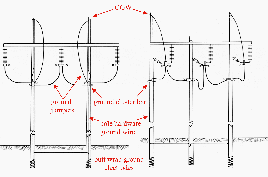
Preferred three-phase grounding applications on wood pole structures using grounding cluster bars are shown in Figures 6 and 7. Grounding cluster bars must be positioned just below the lowest elevation of the lineman’s feet for the work zone (approximately the elevation of the phase conductors) and should be bonded to the pole structure ground leads if provided.


The bar provides convenient point of attachment for protective grounds and a bond to the pole structure ground wire, if provided.
The position of the cluster bar defines the lower boundary of the equipotential work zone on a pole. Figure 5 shows an example of an installed grounding cluster bar.


OGW denotes overhead ground wire. OGWs must be bonded to the worksite grounding system if within reach of linemen. OGWs may be bonded to the cluster bars or to the grounded phase conductors with protective grounds.
Before installing protective grounds, permanent grounding for pole footings should be examined for damage, omission, or other indication of poor continuity between the structural hardware and pole ground electrode.
If in question, a temporary ground rod should be installed next to the pole and bonded to the worksite site grounding system (see Figure 5).


3. Transmission Line Terminal Ground Switches
Transmission line terminal ground switches may be closed in parallel with personal protective grounds at the worksite. Closed line terminal ground switches can help ensure that the protective devices (relays, fuses) operate within the given time/current relationship to quickly isolate the source of accidental electrical energization.
Also, in many cases closed terminal ground switches will reduce the fault current in protective grounds at the worksite, which lowers worker exposure voltages.
Therefore, use of line terminal ground switches is at the discretion of the crew and regional policy. Line terminal ground switches cannot substitute for protective grounds at the worksite.
4. Grounding on Distribution Lines
Protective grounding for distribution lines and aerial cable terminations should be accomplished as shown in Figure 6.


The grounding cluster bar (see photo, Figure 3) must be positioned just below the lowest elevation of the lineman’s feet for the work zone and must be bonded to the neutral conductor and pole ground lead (not shown) if provided.
The position of the cluster bar defines the lower boundary of the equipotential work zone on the pole
Connection of individual protective grounds from the cluster bar to each phase conductor is a permissible alternative, but may produce slightly higher exposure voltage.
Any guy wires within reach of the lineworker should be bonded to the worksite ground system (cluster bar). Ground crew should stay clear (at least 10 feet) of pole grounds, ground rods, and guy wires.
5. Surface Equipment and Vehicle Grounding
This paragraph applies to the grounding and bonding of equipment and vehicles involved in maintenance activities on or near power lines. Vehicles include, but are not limited to, aerial devices, passenger trucks, pole diggers, and cranes.
The purpose of bonding equipment and vehicles to the worksite grounding system (during de-energized work) is to control and minimize transferred touch potentials between the structure, equipment, and vehicle during an accidental energization of the line.
Vehicle and equipment grounds are to be used in conjunction with properly installed personal protective grounds. In no instance should vehicle and equipment grounds be used in place of personal protective grounds.
5.1 Aerial Devices
Aerial devices, whether with an insulated or uninsulated boom, and other maintenance vehicles or equipment that may contact a protective grounded worksite or allow a worker to contact the site, must be bonded to the worksite grounding system.
They must be bonded (grounded) to the structure as the first step in establishing a grounding system.
5.2 Contact with Grounded Vehicles at Worksite
Vehicles and equipment that are bonded to the worksite grounding system can present a hazardous transferred touch voltage with the surrounding ground (earth) surface.
Therefore, any vehicle or equipment bonded to the worksite grounding system (including conductive winch lines) and requiring sustained contact while standing on the ground, must be equipped with an insulated platform or conductive mat bonded to the vehicle or equipment for the operator to stand on.
See Figure 7 below.


Matting and vehicle are bonded to the worksite grounding system, creating an equipotential zone between operator’s hands (vehicle frame) and feet.


6. Grounding Insulated Power Cable
Worksite protective grounding for insulated power cable terminations should be accomplished similar to that required for grounding on power line structures. Cable phase terminals (terminators, potheads, etc.) and shield conductors should be bonded to the worksite grounding system.
The remote (ungrounded) end of the cable MUST be treated as if energized. Although the cable phase conductors are ungrounded (isolated) at the remote (non-worksite) end of the cable, the cable shields are grounded there.
Therefore, workers should take necessary precautions against hazardous step or touch potentials that could develop at the worksite due to a system ground fault at the remote end.
Sources:
- Personal Protective Grounding for Electric Power Facilities and Power Lines by U.S. Department of the Interior Bureau of Reclamation
- High voltage live work and practices manual by Western Power Network


Hello – good presentation.
A mention of applicable standards would be helpful
Thanks
I´m electric design engineer, and I desire know, in concrete, main criteria for using ground wires to proteccion against lightning of overhead electric lines condctors
For distribution lines, is there a rule for the installation of guy wires for straight lines with more than 1 kilometers of length?
Informação técnica muito importante, para a segurança de quem trabalha em redes eléctricas de baixa, média, alta e muito alta tensão.
Scenario: Land Developer owns land started subdivision. AEP comes in halts his development. On the North Side of his property he has wooden transmission lines. Now on the Southern end they are installing new steel transmission lines. 2 high power tension lines running parallel. Then they only work at night. But they got drillers about 15 going 42 ft. in ground to set tower into concrete pad. They got water fracking machines out there with the drill with nonpotable water. There is an agriculture drainage ditch involved. Like right there between the subdivision and the farmer. County wants it widened by 20 ft. each side with a 15ft retainage wall. And then the easement for the tower pad now encroaches on the county property. AEP thinks they will share. But reading not only is there to be at least 35 to 75 ft easement due to high current on each side all the way around the pad but 700 ft. away is safe for humans. How do I go get permits/reports for the soil stabilization. 2 pads have already collapsed on the property. They are using chemicals only found 2 buckets one is a soil concrete stabilizer. Any suggestions.
Nice technical material
I am electrical engineering diploma holder
Good.
The conductor touch the sea water from the generation point by making suitable arrangements.
How to ground marine generatos ?