Protective relay in MV applications
For medium voltage circuit breaker applications, protective relay serve as the “brain” that detects abnormal system conditions and direct the circuit breaker to operate. They also serve to provide specialized protection in low voltage power circuit breaker applications for functions not available in the circuit breaker trip units.
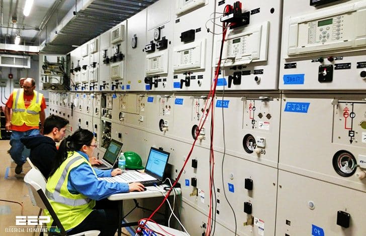
Most modern protective relays are solid-state electronic or microprocessor-based devices, although older electromechanical devices are still available and still work!
Microprocessor-based or solid-state electronic relays offer more flexibility and functionality than electromechanical relays, including the ability to interface with common communications protocols such as MODBUS for integration into a SCADA environment.
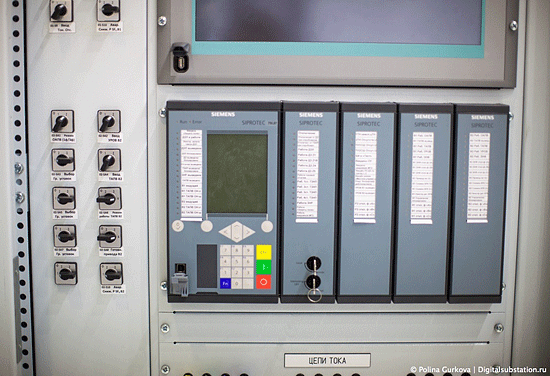

However, they do require “reliable” control power to maintain operation during abnormal system conditions. This reliable control power is most often provided by a DC battery system, although AC UPS-based systems are also encountered.
Electromechanical relays are typically single-phase devices. Solid-state electronic relays are typically available in single-phase or three-phase versions. Microprocessor-based relays are typically three-phase devices.
While electromechanical and solid-state electronic relays typically incorporate one relay function per device, microprocessor-based relays usually encompass many functions in one device. This makes a single microprocessor-based relay capable of performing the same functions that would require several electromechanical or solid-state relays.
This functionality usually makes microprocessor-based relays the best choice for new installations.
Generally, protective relay is not rated for direct connection to the power system where they are applied. For this reason, instrument transformers are used to reduce the currents and voltages to the levels for which the relays are designed. Instrument transformers generally fall into one of two broad categories:
The loads on instrument transformers, such as relays and meters, are known as burdens to distinguish them from power system loads.
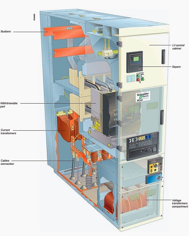

Current transformers (CTs)
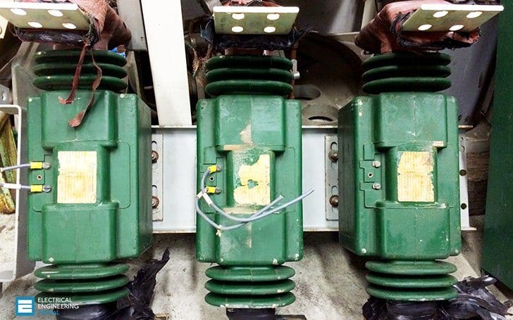
A current transformer consists of a coil toroidally-wound around a ferromagnetic core. The conductor for which the current is to be measured is passed through the center of the toroid. The magnetic field generated by the current through the conductor causes current to flow in the coil.
In essence, a CT may be thought of as a conventional transformer with one primary turn.
Current transformers in the United States typically have 5A rated secondaries, with primary ratings from 10-40,000 A and larger. For relaying applications in industrial facilities, CT ratios are typically 50:5-4000:5.
The classification system consists of a letter and a number. The letter may be C, designating that the percent ratio correction may be calculated, or T, denoting that the ratio correction has been determined by test.

The number denotes the voltage that the CT can deliver to a “standard burden” at 20 times the rated secondary current without exceeding 10% ratio error. As a more accurate alternative, manufacturer-published CT excitation curves may be used to determine the current transformer accuracy.
For relaying application, the issue at hand is the performance of the protective relay during worst-case short-circuit conditions, when the CT secondary currents are the largest and may cause the secondary voltage to exceed the CTs rating due to the voltage developed across the relay input coil.
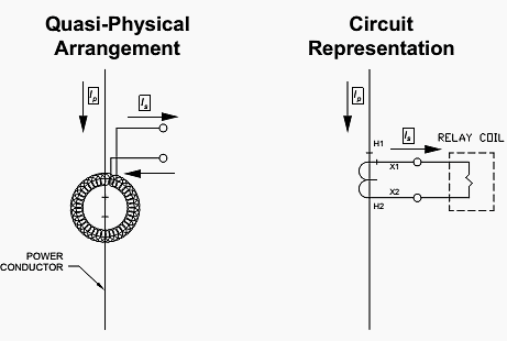

This condition will cause the CT to saturate, significantly changing the ratio and thus the accuracy of the measurement. For cases of severe CT saturation the protective relay may respond in an unpredictable manner, such as not operating or producing “chatter” of its output contacts.
CTs where the power conductor passes through the window formed by the toroidal CT winding are known as window-type CTs. CTs which are designed with an integral bus bar running through device are known as bus-bar type CTs. Other designs, such as wound primary CTs for metering applications and non-saturating air-core CTs, are available.
Go back to Instrument Transformers ↑
Voltage transformers (VTs)
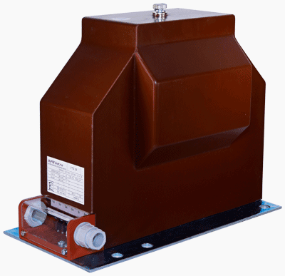
Voltage transformers (VTs) are used to step the power system voltage down to a level that the protective relay can utilize. The operation of voltage transformers is essentially the same as for conventional power transformers discussed in section 2 of this guide, except that the design has been optimized for accuracy. Like current transformers, voltage transformers are assigned accuracy classes by IEEE Std. C57.13.
VT accuracy classes are designated W, X,M Y, Z, and ZZ in order of increasing burden requirements.

Protective relays are classified by function. To make circuit representations easier, each function has been defined and assigned a number by IEEE Std. C37.2. The IEEE standard function numbers are given in Table 1.
Table 2 gives the commonly-used suffix letters to further designate protective functions. These designations can be combined in various ways. For example, 87T denotes a transformer differential relay, 51N denotes a residual ground time-overcurrent relay, 87B denotes a bus differential relay, etc.
Table 1 – Commonly used protective relay device function numbers
| Relay device function number (ANSI Code) | Protection function |
| 21 | Distance |
| 25 | Synchronizing |
| 27 | Undervoltage |
| 32 | Directional Power |
| 40 | Loss of Excitation (field) |
| 46 | Phase balance (current balance, negative sequence current) |
| 47 | Phase-Sequence Voltage (reverse phase voltage) |
| 49 | Thermal (generally thermal overload) |
| 50 | Instantaneous Overcurrent |
| 51 | Time-overcurrent |
| 59 | Overvoltage |
| 60 | Voltage balance (between two circuits) |
| 67 | Directional Overcurrent |
| 81 | Frequency (over and underfrequency) |
| 86 | Lockout |
| 87 | Differential |
Table 2 – Commonly used suffix letters applied to protective relay function numbers
| Suffix Letter | Relay Application |
| A | Alarm only |
| B | Bus protection |
| G | Ground fault protection [relay current transformer (CT) in a system neutral circuit] or generator protection] |
| GS | Ground-fault protection (relay CT is toroidal or ground sensor) |
| L | Line Protection |
| M | Motor Protection |
| N | Ground fault protection (relay coil connected in residual CT circuit) |
| T | Transformer protection |
| V | Voltage |
Go back to Instrument Transformers ↑
Reference // System Protection by Bill Brown, P.E., Square D Engineering Services




This is a very good and interesting team, would like to join.
Any access?
Please send all new information of any type relay
Tres Bon article
I love this job
If possible I will do again
Mr Edvard thanks for the information is very good
Very good article congratulations Eng. Edvard.