Greater than 2400V and less than 69kV
The definition of low voltage fuses is equally applicable to medium voltage fuses. Medium voltage level is defined by standard ANSI C84 as containing standard system voltages from 2400 through 69,000 V, and the high voltage level contains standard system voltages from 115 kV through 230 kV.

The medium voltage level, strictly, is defined by ANSI C84 as greater than 1000 V and less than 100,000 V. Similarly, the high voltage level is defined as greater than 100,000 V through 230,000 V.
The following standards apply to medium voltage fuses:
- IEEE Std. C37.40-2003
- IEEE Std. C37.41-2000
- ANSI C37.42-1996
- ANSI C37.44-1981
- ANSI C37.46-1981
- ANSI C37.47-1981
- IEEE Std. C37.48-1997
- ANSI C37.53.1-1989
Generally, medium voltage fuses can be divided into two major categories: Current-limiting and expulsion.
Current-limiting fuse
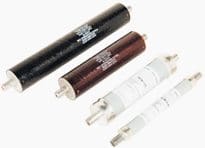
Current-limiting fuse is a current-limiting fuse interrupts all available currents its threshold current and below its maximum interrupting rating, limits the clearing time at rated voltage to an interval equal to or less than the first major or symmetrical loop duration, and limits peak let-through current to a value less than the peak current that would be possible with the fuse replaced by a solid conductor of the same impedance. Same basic definition applies to medium voltage fuses.
Expulsion fuses are defined as follows:
Expulsion fuse
A vented fuse in which the expulsion effect of the gases produced by internal arcing, either alone or aided by other mechanisms, results in current interruption.
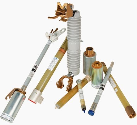
In addition, medium voltage fuses are further classified as power fuses or distribution fuses as follows:
Power fuse
Defined by ANSI C37.42-1996 as having dielectric withstand (BIL) strengths at power levels, applied primarily in stations and substations, with mechanical construction basically adapted to station and substation mountings.
Distribution fuse
Defined by ANSI C37.42-1996 as having dielectric withstand (BIL) strengths at distribution levels, applied primarily on distribution feeders and circuits, and with operating voltage limits corresponding to distribution voltages.
These are further subdivided into distribution current limiting fuses and distribution fuse cutouts, as described below.
Current-limiting fuses interrupt in less than _ cycle when subjected to currents in their current-limiting range. This is an advantage as it limits the peak fault current to a value less than the prospective fault current as described above for low voltage fuses. This provides current-limiting fuses with high interrupting ratings and allows them to protect downstream devices with lower short-circuit ratings in some cases.
Backup current-limiting fuse
A fuse capable of interrupting all currents from its maximum rated interrupting current down to its rated minimum interrupting current.
General purpose current-limiting fuse
A fuse capable of interrupting all currents from the rated interrupting current down to the current that causes melting of the fusible element in no less than 1h.
Full-range current-limiting fuse
A fuse capable of interrupting all currents from its rated interrupting current down to the minimum continuous current that causes melting of the fusible elements.
Due to the limitations of backup and general purpose current limiting fuses, current-limiting power fuses have melting characteristics defined as E or R, defined as follows:
E-Rating
The current-responsive element for ratings 100 A or below shall melt in 300 s at an RMS current within the range of 200% to 240% of the continuous-current rating of the fuse unit, refill unit, or use link. The current responsive element for ratings above 100 A shall melt in 600 s at an RMS current within the range of 220% to 264% of the continuous-current rating of the fuse unit, refill unit, or fuse link.
R-Rating
The fuse shall melt in the range of 15 s to 35 s at a value of current equal to 100 times the R number. Similarly, distribution current-limiting fuses are defined by given characteristic ratings, one of which is the C rating, defined as follows:
C-Rating
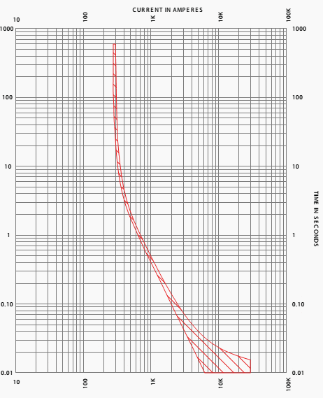
The current-responsive element shall melt at 100 s at an RMS current within the range of 170% to 240% of the continuous-current rating of the fuse unit. A typical time-current curve for an E-rated current-limiting power fuse is shown in Figure 1.
The fuse in Figure 1 is a 125E-rated fuse. Note that the curve starts at approximately 250 A for a minimum melting time of 1000 s.
Note that the boundary of the characteristic, denoting the minimum-melting current, should be further derated to take into account pre-loading of the fuse (consult the fuse manufacturer for details). Note that, as with low voltage fuses, the current-limiting fuse characteristic does not extend below .01 seconds since the fuse would be in its currentlimiting range below this interrupting time.

A current-limiting power fuse consists of a fuse mounting (typically fuse clips) plus the fuse unit itself. These are frequently mounted in metal-enclosed switchgear. A distribution current-limiting fuse may consist of a disconnecting-style holder or clips, plus the fuse unit. Distribution current-limiting fuses may also be provided with under-oil mountings for use with distribution transformers.
They are frequently used for capacitor protection as well, with clips designed to mount to the capacitor.
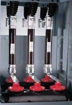
Current-limiting power fuses are typically used for short-circuit protection of instrument transformers, power transformers, and capacitor banks. Table 1 below gives maximum ratings for medium voltage current-limiting power fuses from 2.75 through 38 kV.
Table 1 – Maximum ratings for current-limiting power fuses 2.75 – 38 kV
| Rated Maximum Voltage (kV) | Continuous-Current Ratings (A), Maximum | Short-Circuit maximum interrupting ratings (kA RMS symmetrical) |
| 2.75 | 225,450a,750a, 1350a | 50.0, 50,0, 40.0, 40.0 |
| 2.75/4.76 | 450a | 50.0 |
| 5.5 | 225,400,750a,1350a | 50.0, 62.5, 40.0, 40.0 |
| 8.25 | 125,200a | 50.0, 50.0 |
| 15.5 | 65,100,125a,200a | 85.0, 50.0, 85.0, 50.0 |
| 25.8 | 50,100a | 35.0, 35.0 |
| 38.0 | 35.0, 35.0 |
a Parallel Fuses
During interruption current-limiting fuses produce significant arc voltages. These must be taken into account in selecting equipment. They are typically compared to the BIL level of the equipment, including downstream equipment at the same voltage level. The maximum permissible overvoltages for current-limiting power fuses are shown in Table 2 below:
Table 2 -Maximum permissible overvoltages for current-limiting power fuses
| Rated Maximum Voltage (kV) | Maximum Peak Overvoltages (kV, crest) | |
| 0.5A to 12A | Over 12A | |
| 2.8 | 13 | 9 |
| 5.5 | 25 | 18 |
| 8.3 | 38 | 26 |
| 15.0 | 68 | 47 |
| 15.5 | 70 | 49 |
| 22.0 | 117 | 70 |
| 25.8 | 117 | 81 |
| 27.0 | 123 | 84 |
| 38.0 | 173 | 119 |
In practice, the arc voltages for current-limiting fuses generally indicate the use of the smallest available fuse voltage class for the given system voltage, for example, 5.5 kV fuses instead of 8.3kV fuses for a 4160 V system.
Because medium voltage current-limiting fuses interrupt short circuits without the expulsion of gas or flame, they are widely utilized in a variety of applications.

Power expulsion fuses generally consist of an insulating mounting plus a fuse holder which accepts the fuse refills. The fuse holder may be of the disconnecting or non-disconnecting type. Only the refill is replaced when a fuse interrupts an overcurrent, and if only one phase of a three-phase set interrupted the fault only that fuse need be replaced.
Power expulsion fuses are typically used in substations and enclosed equipment.
Distribution expulsion fuses are generally distribution fuse cutouts, which are adapted to pole or cross arm mounting. They consist of the fuse holder and refill unit. The fuse holder is usually of the disconnecting type. These are typically used as pole-mounted fuses on utility distribution systems.
The exhaust gasses are then emitted from the fuse, accompanied by noise. The exhaust gasses for a boric acid fuse may condensed by an exhaust control device (commonly called an exhaust filter, silencer, or snuffler).
Unlike current-limiting fuses, expulsion-type fuses interrupt high overcurrents at natural current zeros. They are therefore non-current-limiting, and as a result typically have lower interrupting ratings than current-limiting fuses.
Table 3 below shows the maximum continuous current and short-circuit interrupting ratings for refill-type boric-acid expulsion-type power fuses. Because expulsion-type fuses are non-current-limiting, they do not produce the significant arc voltages that current-limiting fuses produce, and thus it is permissible to use a fuse with a larger voltage class than the system, for example, a 14.4 kV-rated fuse on a 4160 V system. This makes expulsion-type fuses particularly useful on systems which may be upgraded in the future to a higher voltage.

However, the lower interrupting ratings of expulsion-type fuses are often an issue vs. current-limiting fuses in light of the fact that the largest expulsion-type fuse interrupting ratings require larger physical dimensions which cannot always be easily accommodated in enclosed equipment. Further, in some cases the expulsion-type fuses prohibit some spacesaving mounting configurations in enclosed equipment that are available with current-limiting fuses.
Table 3 – Maximum continuous current and short circuit interrupting ratings for refill type boric-acid expulsion-type power fuses
| Rated Maximum Voltage (kV) | Continuous-Current Ratings (A), maximum | Short-Circuit maximum interrupting ratings (kA, RMS symmetrical) |
| 2.8 | 200,400,720a | 19.0, 37.5, 37.5 |
| 4.8 | 200,400,720a | 19.0, 37.5, 37.5 |
| 5.5 | 200,400,720a | 19.0, 37.5, 37.5 |
| 8.3 | 200,400,720a | 16.6, 29.4, 29.4 |
| 14.4 | 200,400,720a | 14.4, 29.4, 29.4 |
| 15.5 | 200,400,720a | 14.4, 34.0, 29.4 |
| 17.0 | 200,400,720a | 14.4, 34.0, 25.0 |
| 25.8 | 200,300,540a | 10.5, 21.0, 21.0 |
| 27.0 | 200,300 | 12.5, 20.0 |
| 38.0 | 200,300,540a | 8.45, 17.5, 16.8 |
a Parallel Fuses
E-ratings are used for power expulsion fuses. A typical time-current characteristic for a 125E boric-acid fuse is given in Figure 2 below.
Note that the characteristic extends to the available fault current (in this case, 29.4 kA), unlike that of the current-limiting fuse. It is common practice to treat these as current-limiting fuses so far as the E-rating is concerned, i.e., the maximum load current is usually kept below the E-rating. However, the boric-acid fuse is not subject to damage when loaded above its E-rating, and they are often referred to in the industry as non-damageable due to this fact.
The maximum line-to-line voltage of the system should not exceed the fuse voltage rating. The published interrupting rating for power fuses is typically for a test X/R ratio of 15, and for distribution fuses the test X/R ratio is typically 8; the fuse manufacturer should be consulted for derating factors for X/R ratios above these values.
The manufacturer should also be consulted if the test X/R is in doubt.
Medium voltage fuses provide economical short-circuit protection when applied within their ratings, particularly for transformers, cables, and capacitors. For more sophisticated protection at the medium voltage level, other means must be employed.
Reference: System Protection – Bill Brown, P.E., Square D Engineering Services




Dear Mr/Mrs,
Nice to meet you.
We have a project which it talk about fuse link 24KV , MV , so , I would like you to check document in the attached file as below.
Any problem, Please let me know soon.
Good one