Using capacitors
One of the main benefits of applying capacitors is that they can reduce distribution line losses. Losses come from current through the resistance of conductors. Some of that current transmits real power, but some flows to supply reactive power.

Reactive power provides magnetizing for motors and other inductive loads. Reactive power does not spin kWh meters and performs no useful work, but it must be supplied.
Using capacitors to supply reactive power reduces the amount of current in the line.
Engineers widely use the “2/3 rule” for sizing and placing capacitors to optimally reduce losses. Neagle and Samson (1956) developed a capacitor placement approach for uniformly distributed lines and showed that the optimal capacitor location is the point on the circuit where the reactive power flow equals half of the capacitor var rating.
From this, they developed the 2/3 rule for selecting and placing capacitors. For a uniformly distributed load, the optimal size capacitor is 2/3 of the var requirements of the circuit.
The optimal placement of this capacitor is 2/3 of the distance from the substation to the end of the line. For this optimal placement for a uniformly distributed load, the substation source provides vars for the first 1/3 of the circuit, and the capacitor provides vars for the last 2/3 of the circuit (see Figure 1).
A generalization of the 2/3 rule for applying n capacitors to a circuit is to size each one to 2/(2n+1) of the circuit var requirements. Apply them equally spaced, starting at a distance of 2/(2n+1) of the total line length from the substation and adding the rest of the units at intervals of 2/(2n+1) of the total line length. The total vars supplied by the capacitors is 2n/(2n+1) of the circuit’s var requirements.
So to apply three capacitors, size each to 2/7 of the total vars needed, and locate them at per unit distances of 2/7, 4/7 and 6/7 of the line length from the substation.
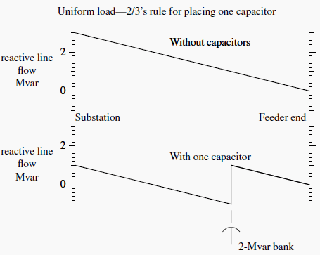
Grainger and Lee (1981) provide an optimal yet simple method for placing fixed capacitors on a circuit with any load profile, not just a uniformly distributed load. With the Grainger/Lee method, we use the reactive load profile of a circuit to place capacitors.
The basic idea is again to locate banks at points on the circuit where the reactive power equals one half of the capacitor var rating.
1. Pick a size
Choose a standard size capacitor. Common sizes range from 300 to 1200 kvar, with some sized up to 2400 kvar. If the bank size is 2/3 of the feeder requirement, we only need one bank. If the size is 1/6 of the feeder requirement, we need five capacitor banks.
2. Locate the first bank
Start from the end of the circuit. Locate the first bank at the point on the circuit where var flows on the line are equal to half of the capacitor var rating.
3. Locate subsequent banks
After a bank is placed, reevaluate the var profile. Move upstream until the next point where the var flow equals half of the capacitor rating. Continue placing banks in this manner until no more locations meet the criteria.
There is no reason we have to stick with the same size of banks. We could place a 300-kvar bank where the var flow equals 150 kvar, then apply a 600-kvar bank where the var flow equals 300 kvar, and finally apply a 450-kvar bank where the var flow equals 225 kvar. Normally, it is more efficient to use standardized bank sizes, but different size banks at different portions of the feeder might help with voltage profiles.
The 1/2-kvar method works for any section of line. If a line has major branches, we can apply capacitors along the branches using the same method. Start at the end, move upstream, and apply capacitors at points where the line’s kvar flow equals half of the kvar rating of the capacitor. It also works for lines that already have capacitors (it does not optimize the placement of all of the banks, but it optimizes placement of new banks).
For large industrial loads, the best location is often going to be right at the load.
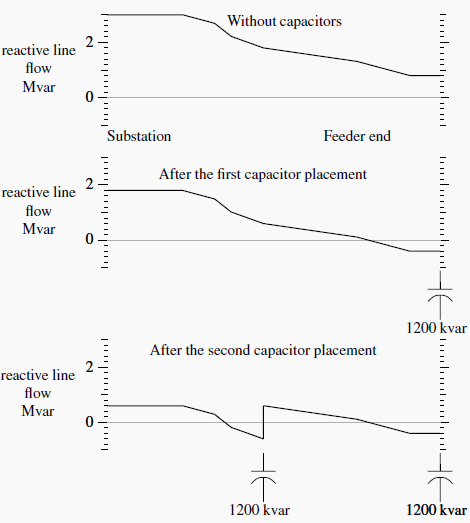
Figure 2 shows the optimal placement of 1200-kvar banks on an example circuit. Since the end of the circuit has reactive load above the 600-kvar threshold for sizing 1200-kvar banks, we apply the first capacitor at the end of the circuit. (The circuit at the end of the line could be one large customer or branches off the main line.) The second bank goes near the middle. The circuit has an express feeder near the start.
Another 1200-kvar bank could go in just after the express feeder, but that does not buy us anything. The two capacitors total 2400 kvar, and the feeder load is 3000 kvar. We really need another 600-kvar capacitor to zero out the var flow before it gets to the express feeder.
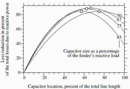
Fortunately, capacitor placement and sizing does not have to be exact. Quite good loss reduction occurs even if sizing and placement are not exactly optimum. Figure 3 shows the loss reduction for one fixed capacitor on a circuit with a uniform load. The 2/3 rule specifies that the optimum distance is 2/3 of the distance from the substation and 2/3 of the circuit’s var requirement.
As long as the size and location are somewhat close (within 10%), the not-quite-optimal capacitor placement provides almost as much loss reduction as the optimal placement.
Consider the voltage impacts of capacitors. Under light load, check that the capacitors have not raised the voltages above allowable standards. If voltage limits are exceeded, reduce the size of the capacitor banks or the number of capacitor banks until voltage limits are not exceeded. If additional loss reduction is desired, consider switched banks as discussed below.
Energy Losses
Use the average reactive loading profile to optimally size and place capacitors for energy losses. If we use the peak-load case, the 1/2-kvar method optimizes losses during the peak load. If we have a load-flow case with the average reactive load, the 1/2-kvar method or the 2/3 rule optimizes energy losses. This leads to more separation between banks and less kvars applied than if we optimize for peak losses.
If an average system case is not available, then we can estimate it by scaling the peak load case by the reactive load factor, RLF:
The reactive load factor is similar to the traditional load factor except that it only considers the reactive portion of the load. If we have no information on the reactive load factor, use the total load factor. Normally, the reactive load factor is higher than the total load factor.

Figure 4 shows an example of power profiles; the real power (kW) fluctuates significantly more than the reactive power (kvar).




Is it possible to transfer the capacitor´s charge to individual batteries placed on individual poles (distribution line) as an external circuit in which the current can then flow constantly – absorbing the distribution line losses (reactive power)? I figure that these storage can then be alternately supplied back at a proper interval.
Thanks any response would be greatly appreciated.
Good day,
antonio
thnx
Good article on capacitor application, but I would recommend staying away from the 2/3 rule. This was developed for a uniformly distributed load with the same conductor size. Neither of these exist in practice.
The 1/2 rule is what should be emphasized. Back to that later.
If we start with the peak reactive load distribution, we can convert that to an average reactive load by multiplying it by the reactive load factor, RLF. So we now have a reactive load distribution based on average conditions over the year.
Select a capacitor bank rating, say 1200 kvar. To optimize the location, place it where the average reactive load equals one-half of that rating or 600 kvar. The result is that the average reactive load on the source side of this location will be reduced by 1200 kvar. The rule is repeated for the next capacitor bank, and so on.
This is the proper rule that should be used for any type of load distribution.