Where/How do we use series capacitors?
Series capacitors are connected in series in the circuit and therefore carry the full transmission line current. The series capacitor is actually a negative reactance in series with a transmission line. The voltage rise across the capacitor is a function of circuit current and acts like a voltage regulator. The negative voltage drop across the series capacitor opposes the voltage drop due to the inductive reactance.

Such effects are very valuable in radial feeders to reduce voltage drop and flicker effects. In the tie lines, the power transfer capability is significantly increased if the series compensation is applied.
Beside usage of series capacitors in power distribution systems, they are used in many applications where the load is fluctuating in nature.
Such applications include resistance welding, arc furnaces, saw mills, rolling mills, crusher load, traction applications, induction generator-wind turbines, and arc welding.
Some details of these applications are discussed below:
- Distribution Systems
- Arc Furnace Power Supply
- Induction Generator Applications
- Traction Applications
- Control of Load Sharing Between Feeders
- Induction Heaters
1. Series Capacitor on Distribution Systems
The starting of a motor draws a large current with a low power factor and causes a momentary voltage dip along the feeder.
The voltage dip is sudden and lasts for a few seconds until the motor reaches the rated speed. The voltage flicker due to motor starting is objectionable in certain cases. Such a problem exists with large motors, welding equipment, furnaces, and other fluctuating loads.
The traditional solutions to the voltage flicker problem are re-conductoring the feeder, upgrading the system voltage, providing a new feeder, constructing a new substation or installing other compensating equipment across the load.
The series capacitor is a viable solution to the flicker problem.
In order to have better results, the series capacitor location has to be carefully chosen. Further, the reactance of the series capacitor should be smaller than the total source reactance in order to avoid overcompensation.
A single line diagram of such a system is shown in Figure 1, along with the corresponding block diagram.


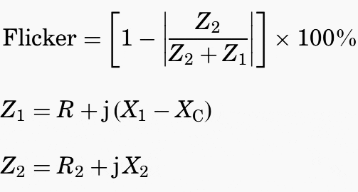

where:
- Z1 = Impedance of the transformer, feeder, and series capacitor
- Z2 = Impedance of the feeder and starting motor
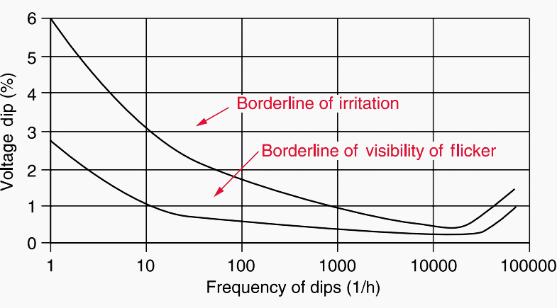
Such a flicker reduction approach is applicable for a utility distribution system. The calculated flicker value can be compared with the acceptable flicker
levels available in Figure 2.

2. Series Capacitance in Arc Furnace Power Supply
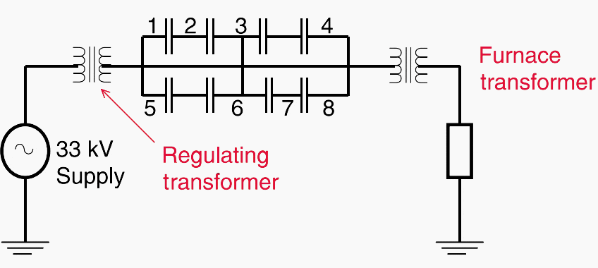
A single line diagram of an arc furnace installation with series capacitor scheme is shown in Figure 3. The system consists of a 30 MVA arc furnace, supplied through a 30 MVA furnace transformer.
The series capacitor is connected in an H-configuration and is protected by a shunt bypass arrangement consisting of a bypass circuit breaker along with spark gaps.
The current required in the arc furnace during the melting process is fluctuating and the series capacitor offers a means of smoothing the current flow.

3. Series Capacitors for Induction Generator Applications
The induction machine is a very simple and robust device. As a motor, it performs very well and as a generator it has limitations due to the absence of excitation.
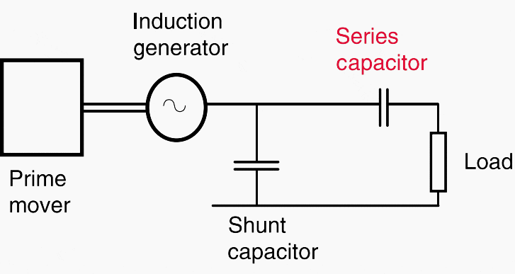
The excitation requirements can be supplied through shunt capacitors but self-excitation limits the size of the capacitor equipment.
Also, for better performance, the capacitor has to be switched.
A single line diagram of such a scheme is shown in Figure 4 below.

4. Series Capacitor for Traction Applications
In traction systems, the system supply voltages are limited due to the presence of tunnels, bridges, etc. As a rule of thumb, a 20 mile line is acceptable with 25 kV and a 40 mile line for 50 kV system voltages.
If the distance between the substations is short and if the train loading is high, the voltage drop imposes a limit on the performance of the locomotive. With heavy loading on the long lines, the performance is again limited by the voltage drop.
Some viable solutions to the voltage drop may be to add more substations, low impedance catenary, shunt capacitors, series capacitors, or higher catenary voltage.
The series capacitor was used in the Black Mesa and Lake Powell Railroad at 50 kV system voltage. In this coal-haul railroad, two trains were to operate with three 6,000 hp locomotives per train. The catenary was fed radially for 78 miles with no intermediate substations.
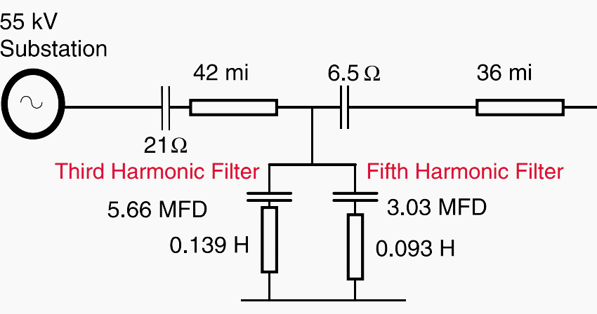

The load of 36 MVA was simply far too great to supply over 78 miles by one substation. The shunt and series capacitor scheme used to compensate the line is shown in Figure 5. The shunt capacitor-supported filter bank is installed at 42 miles from the substation.
The harmonic filters are tuned to 3rd and 5th harmonics.
The series capacitors are 21 Ω and 6.5 Ω, installed at the substation and at the 42 mile location. The system was installed in early 1980.
5. Control of Load Sharing Between Feeders
Consider an overhead transmission line or distribution line to be reinforced by a second circuit operating in parallel. If the second circuit is of different length with different impedance, then there may be a load sharing problem.
This concept is illustrated in Figure 6 below.
Example
Consider an 11 kV, 60 Hz, three-phase distribution line between X and Y as shown in Figure 6 below.
The reactance of line 1 is 4 Ω/phase and the reactance of the second line is 6 Ω/phase.
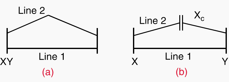

The load supplied at substation Y is 5,000 kVA. Calculate the current through each line. In order to ensure equal load current through each feeder, a series capacitor bank is proposed at the middle of line 2.
Calculate the reactance of the series capacitor. Ignore the effect of resistance and assume that the conductors in both circuits are the same.
Solution
- Reactance of line 1 = 4 Ω/phase
- Reactance of line 2 = 6 Ω/phase
- Total load current (5,000 kVA /1.732 11 kV) = 262 A/phase
- Current through line 1 (262 6 / 10) = 157.2 A/phase
- Current through line 2 (262 4 / 10) = 104.8 A/phase
Since both line conductors are the same, an equal current distribution is expected. In order to ensure equal current distribution through the conductors, a series capacitor is proposed, as shown in Figure 6b. The expected current in line 1 is equal to the current in line 2, 131 A.
- The new reactance of line 2 = 4 Ω/phase
- Reactance of the series capacitor bank (6 − 4) Ω = 2 Ω/phase
6. Capacitors for Induction Heaters
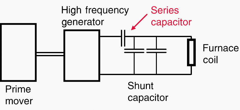
Induction heaters are designed to heat ferrous or non-ferrous materials. A typical single line diagram of a power supply for an induction heater is shown in Figure 7.
A motor generator set can be used to generate the required high frequency voltage. The induction coil can be supplied through a series capacitor. The power factor of the induction furnace is always low and can be improved by using shunt capacitors.
The series capacitor is used to improve the voltage regulation. A typical voltage range for a high voltage capacitor for induction heating is 2.5–6 kV single-phase or three-phase. The heater ratings are 1.5–4 MW.

To conclude…
The series capacitors in the radial system can be used to improve the voltage profile on distribution systems. The numerical examples show how the power transfer is increased and how the flicker problem can be controlled.
Other applications of the series capacitor, such as the arc furnace, induction generator and the traction system performance improvement, are excellent example of how overall power quality can be efficiently increased.
Sources: Power system capacitors by Ramasamy Natarajan



Kindly advice me on how I can easily understand the contral circuit on a star delta connection. especially on an automatic changeover contral
Kindly advice me on how I can easily understand the contral circuit on a star delta connection especially on an automatic changeover contral
nice information..
nice subject..lot of information we are getting
Dear sir Please provide the arc flash calculator.