Home / Technical Articles / Shaping and connecting rigid busbars in low voltage switchgear
Estimated Study Time: 8 minutes
Busbars – machining, bending and shaping
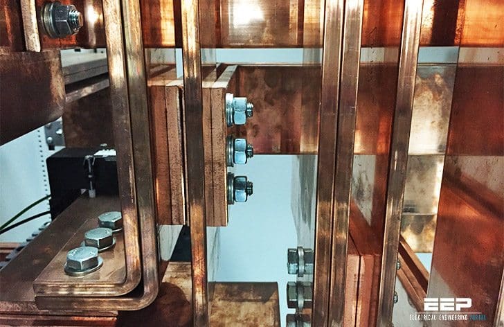
The busbars constitute the real “backbone” of every low voltage switchgear. The main busbar and branch busbars supply and distribute the energy. Creating busbars generally involves machining, bending and shaping which require a high degree of expertise to avoid weakening the bars or creating stray stresses.
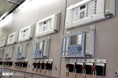
Shaping and connecting rigid busbars in LV switchgear (photo credit: Edvard Csanyi)
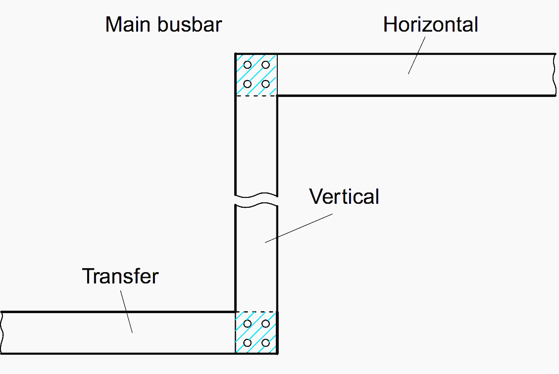
The same applies to connections between bars, whose quality depends on the sizes and conditions of the contact areas, and the pressure of this contact (number of screws and effectiveness of tightening).
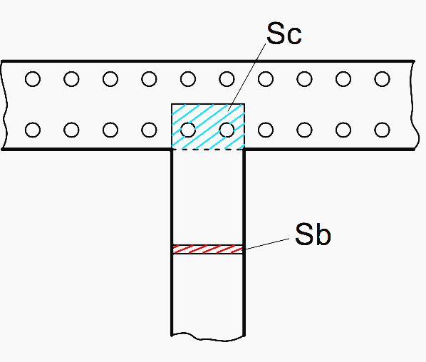
The contact area (sc) must be at least 5 times the cross-section of the bar (Sb). Sc > 5 × Sb for main busbar continuity links, it is advisable to establish contacts along the entire length of the bar in order to ensure optimum heat transfer.
Figure 1 – Busbar contact area and cross-section
For branch busbars, the contact area can be smaller, complying with the condition Sc > 5 × Sb. For equipment connection plates, contact must be made over the whole surface of the plate for use at nominal current.
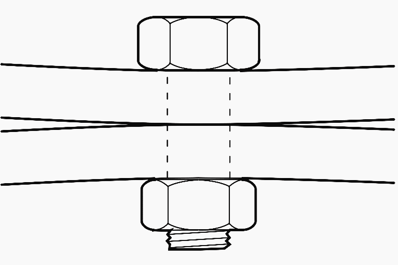
The contact pressure between bars is provided using screws whose size, quality, number and tightening torque are selected according to the current and the sizes of the bars.
Too high a tightening torque or not enough screws can lead to distortions which reduce the contact area!! It is therefore advisable to distribute the pressure by increasing the number of tightening points and using wide washers or back-plates.
Figure 5 – Busbars contact pressure
Devices to prevent loosening:
Figure 6 – Devices to prevent loosening
Applying a mark (paint, brittle coating) will show any loosening and can also be used to check that tightening has been carried out correctly (tell-tale)
Figure 7 – Applying a mark (paint, brittle coating) Figure 8 – Left: Connection on 120 x 10 bars (4000 A); Right: Double connection: 100 x 10 bars (3200 A) and 80 x 10 bars (2500 A) on common 120 x 10 bars
Recommended screws and minimum characteristics
I [A]
Bar width [mm]
Number of screws
∅ Screw [mm]
Minimum quantity
Tightening torque [Nm]
1 bar
2+ bars
≤ 250
–
≤ 25
1
M8
8-8
15/20
2
M6
8-8
10/15
≤ 400
–
≤ 32
1
M10
6-8
30/35
≤ 630
–
≤ 50
1
M12
6-8
50/60
2
M10
6-8
30/35
2
M8
8-8
15/20
800
1250
≤ 80
4
M8
8-8
15/20
4
M10
6-8
30/35
1000
1600
≤ 100
4
M10
6-8
30/35
2
M12
6-8
50/60
1600
2500
≤ 125
4
M12
6-8
50/60
Tightening torques that are too high lead to the limit of elasticity of the bolts being exceeded and creeping of the copper.
Apart from pronounced oxidation (significant blackening or presence of copper carbonate or “verdigris”), bars do not require any special preparation.
Cleaning with acidified water is prohibited, as, apart from the risks, it requires neutralisation and rinsing. Surface sandin (240/400 grain) can be carried out, complying with the direction of sanding so that the “scratches” on bars that are in contact are perpendicular.
Copper is a soft, “greasy” or “sticky” metal in terms used in the trade. shaping is generally carried out dry, but lubrication is necessary for high-speed cutting or drilling operations (up to 50 m/mn).
Figure 10 – Sawing (8D medium tooth) in a clamping vice Figure 11 – It is possible to make holes with drills for steel, but it is preferable to use special drills (with elongated flutes for easy detachment of chips)
The hydraulic punch is used to make precision holes easily … and with no chips.
It is strongly recommended that a full-scale drawing is made of the bars, in particular for bends and stacking of bars.
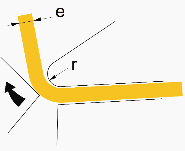
Figure 12 – Bending busbars
The bars are separated by their thickness “e”. The total centre line length before bending is the sum of the straight parts (L1 + L2) that are not subject to any distortion and the length of the curved elements on the neutral line (in theory at the centre of the thickness of the metal).
Bending to 90°
l = (2πR) / 4 = (2r + e) × π / 4
Useful formula: l = R × 1.57
Figure 13 – Bending busbars to 90°
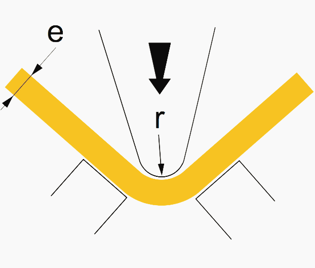
Bending to any angle α
l = (2r + e) × π × (180 – α) / 360
Where:
r is bending radius (or radius of the tool)
R is radius to the neutral line R = r + e/2
l is length to the neutral line
Figure 14 – Bending to any angle α
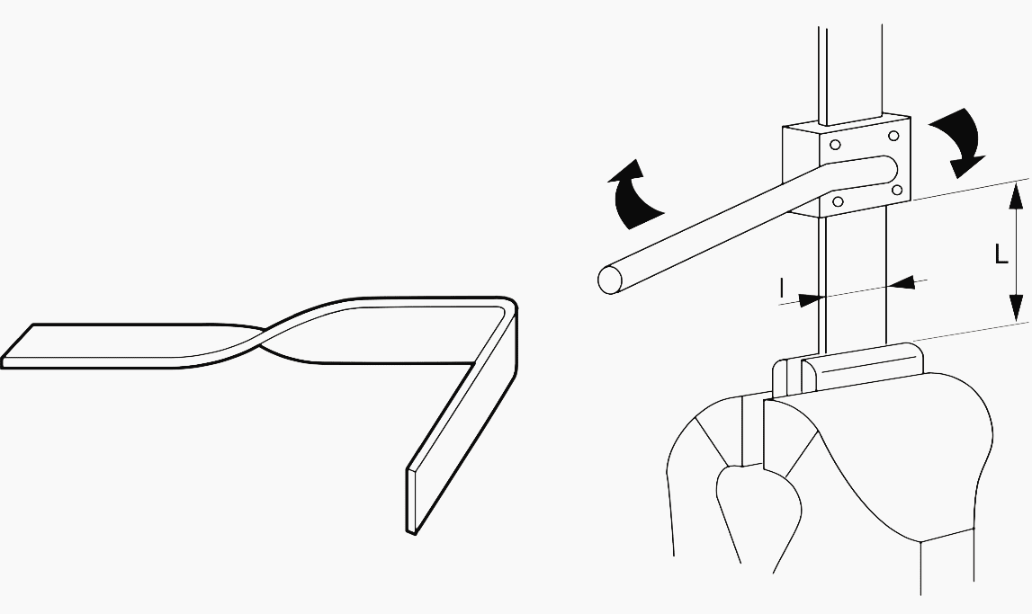
Creating a twist
The length L of the twist is at least twice the width l of the bar:
Figure 15 – Creating a twist
Calculation note!
The calculation must be carried out based on the tool used and its actual bending radius r.
Bending on bending machine: r = 1 to 2e
Figure 16 – Bending on bending machine: r = 1 to 2e
This technical article is protected by U.S. and international copyright laws. Reproduction and distribution of PDF version of this technical article to websites such as Linkedin, Scribd, Facebook and others without written permission of the sponsor is illegal and strictly prohibited.
Get access to premium HV/MV/LV technical articles, electrical engineering guides, research studies and much more! It helps you to shape up your technical skills in your everyday life as an electrical engineer.
Hi, I'm an electrical engineer, programmer and founder of EEP - Electrical Engineering Portal. I worked twelve years at Schneider Electric in the position of technical support for low- and medium-voltage projects and the design of busbar trunking systems.
I'm highly specialized in the design of LV/MV switchgear and low-voltage, high-power busbar trunking (<6300A) in substations, commercial buildings and industry facilities. I'm also a professional in AutoCAD programming.
Hi, in this article “https://electrical-engineering-portal.com/shaping-connecting-rigid-busbars”, what does the pressures 1bar and 2+bars referring to, in the table for “Recommended screws and minimum characteristics”, please?
I would like to inform you taht I have a premium accounto with EEP but every time that a new Technical guide, article, studio or paper comes to my computer I can not access directly to it . every time I have to go ito your systens with my Email and password an then when I want to return to paper, technical guide, article or technicalstudio that you have sent to me the systems don not permit to access and I have to look for in all you webpage Before, in the beggining when my subscriptions beggins, I had not that problem, all was very easy. I think the access should be easier ad quicker . Thanks in advance for your help
Ask a question ,What’s the meaning in the table “Recommended screws and minimum characteristics” of Minimum quantity 8-8、6-8? Can you explain it clearly? thanks
I would like to have use of Belleville washers addressed. Our physical plant specs require used of these washers to connect sections of switchgear together.


Hi, in this article “https://electrical-engineering-portal.com/shaping-connecting-rigid-busbars”, what does the pressures 1bar and 2+bars referring to, in the table for “Recommended screws and minimum characteristics”, please?
Please I need calculation for numbers of cooling fans for power transformers. (ONAF)
Dear Sirs
I would like to inform you taht I have a premium accounto with EEP but every time that a new Technical guide, article, studio or paper comes to my computer I can not access directly to it .
every time I have to go ito your systens with my Email and password an then when I want to return to paper, technical guide, article or technicalstudio that you have sent to me the systems don not permit to access and I have to look for in all you webpage
Before, in the beggining when my subscriptions beggins, I had not that problem, all was very easy. I think the access should be easier ad quicker .
Thanks in advance for your help
Thank you for posting this article!
Dear Sirs.
Above information (Sb>5*Sc….) that what standard belongs to? (Example: IEC?, JIS?, NFC?…)
Vo,
One of the standard in use is DIN 43670
Ask a question ,What’s the meaning in the table “Recommended screws and minimum characteristics” of Minimum quantity 8-8、6-8?
Can you explain it clearly? thanks
Thanks for this sharing, it’s very useful.
Thank you for this sharing , very interesting article
Thank you for the information. It was very helpful
I would like to have use of Belleville washers addressed. Our physical plant specs require used of these washers to connect sections of switchgear together.
Thanks, your article very informative and contains professional information. Which is useful for the engineers working in the field.
Thank you for the articles being posted.
I am an electronics person working in Maintenance of UPS systems.
Thanks once gain.