
Correct size of motors and converters
Manufacturers of electric motors and frequency converters have evolved various methods for quickly selecting the size of motors and frequency converters for a particular machine load. The same basic procedure is used by most applications engineers.
 Sizing the motor and frequency converter for a particular machine load (photo credit: focusondrives.com)
These days, applications selections are usually done on the basis of PC based software. However, it is important for engineers to clearly understand the selection procedure.
4 selection principles
The five following selection principles are recommended:
Selection principle 1 //
First, the type and size of motor should be selected. The number of poles (basic speed) should be chosen so that the motor runs as much as possible at a speed slightly above the base speed of 50 Hz.
This is desirable because:
- The thermal capacity of the motor improves when f ≥ 50 Hz because of more efficient cooling at higher speeds.
- The converter commutation losses are at minimum when it is operating in the field weakening range above 50 Hz.
- For a constant torque load, a larger speed range is obtained when the motor operates well in the field weakening range at the maximum speed. This means that the most efficient use is made of the torque/speed capability of the variable speed drive.

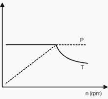
Typical torque and power curves in a constant power/torque application
This could mean cost savings in the form of a smaller motor and converter. - Although many manufacturers claim that their converters can produce output frequencies of up to 400 Hz, these high frequencies are of little practical use except for very special (and unusual) applications. The construction of standard cage motors and the reduction of the peak torque capability in the field weakening zone, restrict their use at frequencies above 100 Hz.The maximum speed at which a standard squirrel cage motor can be run should always be checked with the manufacturer, particularly for larger 2-pole (3000 rev/m) motors of more than 200 kW. The fan noise produced by the motor also increases substantially as the speed of the motor increases.
- A comparison of the torque produced by a 4 pole and a 6 pole motor is shown in Figure 1. This illustrates the higher torque capability of the 6 pole machine.
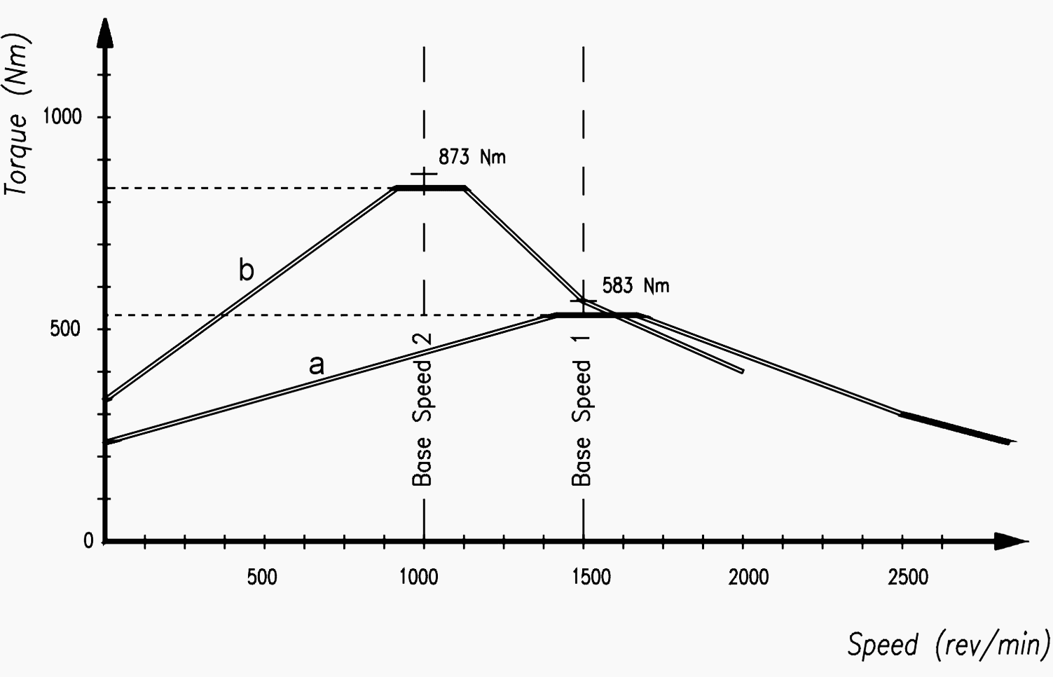
- 90 kW 4 pole motor (1475 rev/min)
- 90 kW 6 pole motor (985 rev/min)
Selection principle 2 //
The selection of an oversized motor just to be ‘safe’ is not usually advisable because it means that an oversized frequency converter must also be selected. Frequency converters, particularly the PWM-type, are designed for the highest peak current value, which is the sum of the fundamental and harmonic currents in the motor.
The larger the motor, the larger the peak currents.
Selection principle 3 //
Once the motor has been selected, it is reasonably easy to select the correct converter size from the manufacturer’s catalogue. They are usually rated in terms of current (not kW) based on a specific voltage. This should be used as a guide only, because converters should always be selected on the basis of the maximum continuous motor current.
Although most catalogues are based on the standard IEC motor power ratings (kW), motors from different manufacturers have slightly different current ratings.
Selection principle 4 //
Although it seems obvious, the motor and converter should be specified for the power supply voltage and frequency to which the variable speed drive is to be connected.
In recent years, AC converters are manufactured for use at 3.3 kV and 6.6 kV. Frequency converters are designed to produce the same output voltage as that of the supply, so both the motor and the converter should be specified for the same base voltage.
Although the output frequency of the converter is variable, the input frequency (50 Hz or 60 Hz) should be clearly specified because this can have an effect on the design of inductive components.
Reference // Practical Variable Speed Drives and Power Electronics by Malcolm Barnes CPEng, BSc(ElecEng), MSEE, Automated Control Systems, Perth, Australia (Purchase hardcopy from Amazon)
Related electrical guides & articles


Edvard Csanyi
Hi, I'm an electrical engineer, programmer and founder of EEP - Electrical Engineering Portal. I worked twelve years at Schneider Electric in the position of technical support for low- and medium-voltage projects and the design of busbar trunking systems.I'm highly specialized in the design of LV/MV switchgear and low-voltage, high-power busbar trunking (<6300A) in substations, commercial buildings and industry facilities. I'm also a professional in AutoCAD programming.
Profile: Edvard Csanyi

Ing muchas gracias excelente tema
De gran utilidad.
Dear Edvard Csanyi,
In this post, you are mentioned the positive points of run the motor F>50Hz. But what are the negative points of run the motor F>50Hz related to motor? kindly provide your ideas in comments sir.
Hi Edward Csnayi,
Your articles are very valuable and well reasearchged.I am very much fan of your informative articles covering variety of subjects in Electrical Engineering.
Keep it up.
Thanks