High inrush making current
Switching of medium voltage capacitor banks and filter circuits poses special demands on the circuit-breaker. Potentially critical impacts are the inrush current and the stress of the recovery voltage. This technical article deals with the requirements of capacitor banks without reactors, capacitor banks with inrush limiting reactors (reactor-capacitor units), and filter circuits.

Special attention will be paid to measures that have to be taken to limit the inrush making current and how a circuit breaker is dealing with the switching of capacitor banks, the permissible stress it endures.
- Switching of capacitor banks (without reactor)
- Switching of reactor-capacitor combinations
- Permissible inrush current
- Measures to limit the inrush making current
- Permissible voltage at the circuit-breaker
- Determination of the voltage on the load side of the breaker
- Check for permissible stress on the circuit-breaker
1. Capacitor banks (without reactor)
Table 1 – Switching of capacitor banks (without reactor)
| Duty: | – Single capacitor bank – Paralleling of capacitors (back-to-back switching) |
| Current: | – Up to 1.43 times the capacitor rated current at the fundamental component (factor 1.43 includes harmonics and tolerances of the capacitance). – On back-to-back switching, 100 times the rated current of the capacitor may occur. |
| cos φ: | – Leading |
| Remarks: | When paralleling, a high inrush current (Ie) with a high rate of rise (considerably above the value of a short-circuit) may occur. The permissible inrush current (peak value) of a circuit-breaker depends on the geometry and the mechanical travel characteristics of the breaker contact and should not exceed the following values:
When closing on a single capacitor bank, the inrush current does not exceed the peak value and the rate of rise of a power-frequency short-circuit, which the breaker must be capable to cope with in any case. |
| Measures: | Circuit-breaker must feature a very low restrike probability and comply with class C 2 according to IEC 62271-100. Single capacitor banks do not require additional measures. When back-to-back switching of capacitor banks, the inrush current must be determined and where applicable to be limited. |
Go back to the Contents Table ↑
2. Reactor-capacitor combinations
Table 2 – Switching of reactor-capacitor units and filters
| Duty: | – Single capacitor bank – Paralleling of capacitors (back-to-back switching) |
| Current: | – Up to the rated current of the capacitor bank or the filter |
| cos φ: | – Leading |
| Remarks: | After the opening operation, the voltage on the capacitor side is higher than the system voltage (Figure B-18), so that the recovery voltage is higher in contrast to capacitors without a reactor. The rated voltage of the breaker must not be exceeded by this effect. When paralleling, high inrush currents (Ie) with a high rate of rise may occur, depending on the reactor ratings. However, the inrush current does not exceed the permissible limits of breaker and capacitor if reactors are used (usually tuned to between 4th and 5th harmonic). |
| Measures: | If the voltage at the breaker exceeds its rated value, either a breaker of a higher rated voltage level or 2 series-connected breakers have to be used. Circuit-breaker must feature a very low restrike probability and comply with class C 2 according to IEC 62271-100. When back-to-back switching of capacitor banks, the inrush current must be determined and where applicable to be limited. |
Go back to the Contents Table ↑
3. Permissible inrush current
The permissible inrush current depends on the ratings of both the circuit-breaker and the capacitor bank.
Capacitor bank:
Independent of the circuit-breaker, the peak value of the inrush current may not exceed 100 times the rated normal current of the capacitor, in order to limit the effect of the electrodynamic forces. Factor 100 is a general rule only, at high switching rates the standard IEC 60871-1-07 (Shunt capacitors for a.c. power systems having a rated voltage above 1000V – Part 1: General) recommends limiting the inrush current to lower values.
Otherwise, the inrush current can increase to undue values if the polarity of the system voltage is in opposition to the residual charge.
Circuit-breaker:
In order to avoid inadmissible stress and wear of the contact pieces, permissible limits of the inrush current must be observed. For Siemens circuit-breakers the following inrush currents are permissible without reservations:
- Ie ≤ 5 kA for tulip contacts (SF6 or minimum-oil circuit-breakers)
- Ie ≤ 10 kA for flat contacts (vacuum circuit-breakers)
Regarding flat contacts, the limit value is founded on the tendency to contact welding if the inrush current does not decay rapidly enough during the pre-arcing time (1 … 2 ms) of the contact closing travel. Inrush currents above the limits mentioned above require an agreement with the manufacturer.
On the other hand, if the inrush current decays rapidly below the limit, considerably higher initial values of the inrush current are permissible (see Figure 1).
Figure 1 – Permissible back-to-back inrush making current dependent on the time constant


The limit value 20 kA of the inrush making current marks the rated back-to-back inrush making current for capacitor banks recommended by the circuit-breaker standard (IEC 62271-100-04 – High-voltage switchgear and controlgear – Part 100: Alternating-current circuit-breakers).
It is extremely difficult to determine the resistive component since the skin effect reduces the active conductor cross-section at some kHz frequency of the back-to-back inrush making current. An assessment by means of the inductance between the capacitor bank gives a hint of whether the inrush current lies in the critical range and requires detailed calculation.
Go back to the Contents Table ↑
4. Measures to limit the inrush making current
There are two possible ways to reduce a high inrush making current and to move it into the permissible region:
- The limitation of the inrush current to ≤ 10 kA (or ≤ 5 kA) by means of a reactor.
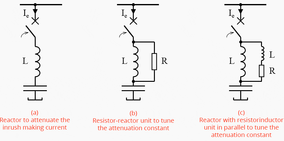
- The reduction of the time constant (attenuation constant) by means of a resistor-inductor unit in parallel with the reactor. However, this measure is only convenient for existing reactor-capacitor units.
For a given reactive power and inductance between the capacitor banks, the inrush making current on back-to-back switching can be read from the graphs (Figure 2). If the inrush current is too high, the diagram shows the inductance which is required to keep the inrush current below the limit.
Figure 2 – Back-to-back inrush making current of two capacitor banks, depending on the inductance between the banks
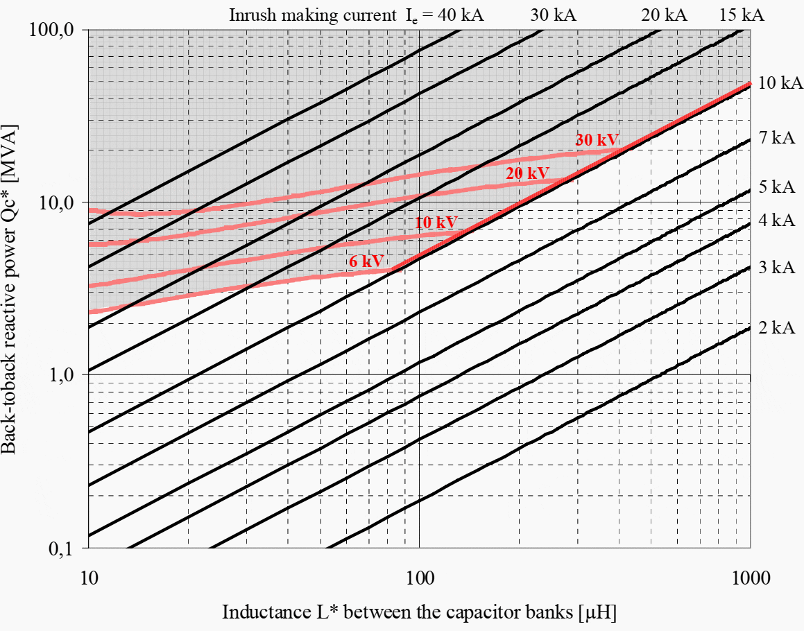

The difference between the existing and the required inductance should be installed as an additional reactor; see (a), Figure 3. The red borderlines (Figure 2) mark the area (grey) for 6 kV to 30 kV operating voltages within which the attenuation constant of the inrush-making current is too high. For these borderlines, a Q-factor (quality factor) 60 of the parallel oscillating circuit is presumed.
The back-to-back reactive power results from the series connection of the two capacitor banks (Figure 1).
Qc* = (Qc1 × Qc2) / (Qc1 + Qc2)
The inductance between the capacitor banks consists of the inductances of the connecting conductors and the switchgear assembly. The following values can be presumed: for L1 and L2 insert the values of the relevant cables/bars (in the range of ca. 0.3 … 0.7 µH/m).
L* = L1 + L2 + Ls
For each functional unit (panel) of the switchgear assembly insert 2 µH for the busbar, and 5 µH for the two feeders (including current transformers); n = number of functional units (panels) between the capacitor bank feeders.
Ls ≈ 5μH + n × 2μH
Figure 3 – Methods to limit the inrush making current
A reactor that can be freely selected (Figure 3a) is the easiest method to limit the inrush-making current. In the case, a reactor is already installed or planned but the inrush current is still too high, a resistor in parallel (Figure 3b) can tune the attenuation constant.
The resistance, however, may vary in a small range only. It must neither be too high (to be efficient) nor too low (to avoid thermal overload of the resistor). An L-R impedance in parallel to the reactor (Figure 3c) facilitates more exact tuning.
In any case, the damping elements need to be individually planned for the given installation.
Figure 3 – Methods to limit the inrush making current

Go back to the Contents Table ↑
5. The permissible voltage at the circuit-breaker
When filter circuits or reactor-capacitor units are switched off the recovery voltage across the breaker is higher than when other loads are switched. The reasons for this are on the one hand the properties of the combination of reactor + capacitor and on the other hand, the fact that these filters are used in systems where the voltage stress on the equipment is increased by distorted voltage due to harmonic oscillations.
The voltage on the load side of the breaker can exceed the rated value, even if the system voltage is below the rated breaker voltage because the capacitor voltage appears at the breaker after switching off. The capacitor voltage in turn is higher than the system voltage; see next Section 6 (Figure 4).
Consequently, it must be checked very accurately whether the stress on the circuit-breaker is within the permissible range. If the capacitor voltage (Uc) exceeds the rated breaker voltage (Ur), a breaker of the next higher voltage rating must be used; e.g. a 36 kV breaker instead of a 24 kV breaker, or two breakers must be connected in series.
The following section summarises how the voltage stress caused by filters and reactor-capacitor units are determined, and which parameters need to be checked regarding the circuit-breaker.
Suggested reading – MV/HV switchgear switching capability for specific applications
MV/HV switchgear (circuit breaker) switching capability and suitability for specific applications
Go back to the Contents Table ↑
6. Determination of the voltage on the load side of the breaker
Immediately after switching off the voltage UF is present on the load side of the breaker, which can be determined as described below.
Figure 4 – Voltage at a filter or a reactor-capacitor unit


Where:
- UN – Voltage of network
- UF – Voltage at the filter
- UL – Voltage across the reactor
- UC – Voltage at the capacitor
- IF – Filter current
- L – Reactance
- C – Capacitance of capacitor bank
- Filters frequency: fF = 1 / 2π√LC
- Filter- / system frequency ratio ν = fF / fN , where ν is Harmonic number (ordinal number)
When the circuit is closed the voltage on both sides of the circuit-breaker, filter and busbar is the same (UF = UN). Immediately after switching off (marked by subscript “o”), the capacitor voltage appears at the breaker since the voltage across the reactor drops to zero. Thus the voltage on the breaker load side is UFo = UCo
After the opening operation the filter voltage is equal to the capacitor voltage which is calculated with the harmonic number ν:
UFo = UCo = UN × ν2/(ν2−1)
For example: ν = 5, i.e. filter frequency 250 Hz:
UFo = UCo = UN × 52/(52−1) = 1,042 × UN
This means that immediately after switching off the voltage on the load side of the circuit-breaker is 4.2 % higher than the system voltage on the busbar side.
Go back to the Contents Table ↑
7. Check for permissible stress on the circuit-breaker
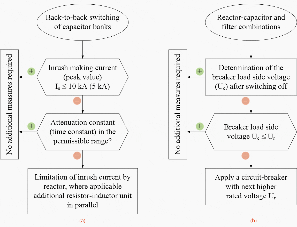
If the back-to-back inrush making current is below the permissible peak values or the attenuation of the current is strong enough, no additional measures are required. Otherwise, a detailed assessment as described in Section 4 (Measures to limit the inrush making current) has to be carried out.
With filters or reactor-capacitor units, the voltage on the load side of the circuit-breaker must not exceed the rated value at the instant of switching off.
There is a particular danger if the operating voltage of the system is very close to the rated voltage and at a low ordinal number of the harmonics.
Figure 5 – (a) Inrush current check; (b) Voltage check

Go back to the Contents Table ↑
Source: Switchgear application guide by Siemens






i am highly impressed and i must confess that i learnt a lot on this site. in fact, i can say that i am not the same person in terms of electrical knowledge before i discover this site, i have gain a lot here. i wish i can have the opportunity to work with you practically so that i can consolidate my knowledge. thank you and remain blessed.
Send me PF calculation