

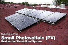
Stand-alone PV (photovoltaic) systems are used when it is impractical to connect to the utility grid. Common standalone systems include PV-powered fans, water pumping systems, portable highway signs, and power systems for remote installations, such as cabins, communications repeater stations, and marker buoys. The design criteria for stand-alone systems is generally more complex than the design criteria for utility interactive systems, where most of the critical system components are incorporated in the PCU.
The PV modules must supply all the energy required unless another form of backup power, such as a gasoline generator, is also incorporated into the system. Stand-alone systems also often incorporate battery storage to run the system under low sun or no sun conditions.
PV-Powered Fans

Perhaps the simplest of all PV systems is the connection of the output of a PV module directly to a DC fan. When the module output is adequate, the fan operates. When the sun goes down, the fan stops. Such an installation is reasonable for use in remote bathrooms or other locations where it is desirable to have air circulation while the sun is shining, but not necessarily when the sun goes down.
The advantage of such a system is its simplicity. The disadvantage is that it does not run when the sun is down, and under low sun conditions, the system operates very inefficiently due to a mismatch between the fan I-V characteristic and the module I-V characteristic that results in operation far from the module maximum power point. If the fan is to run continuously, or beyond normal sunlight hours, then battery storage will be needed. The PV array must then be sized to provide the daily ampere-hour (Ah) load of the fan, plus any system losses. A battery system must be selected to store sufficient energy to last for several days of low sun, depending upon whether the need for the fan is critical, and an electronic controller is normally provided to prevent overcharge or overdischarge of the batteries.
PV-Powered Water Pumping System

If the water reservoir is adequate to provide a supply of water at the desired rate of pumping, then a water pumping system may not require battery storage. Instead, the water pumped can be stored in a storage tank for availability during low sun times. If this is the case, then the PV array needs to be sized to meet the power requirements of the water pump plus any system losses. If the reservoir provides water at a limited rate, the pumping rate may be limited by the reservoir replenishment rate, and battery storage may be required to extend the pumping time.
While it is possible to connect the PV array output directly to the pump, it is generally better to employ the use of an electronic maximum power tracker (MPT) to better match the pump to the PV array output. The MPT is a DC–DC converter that either increases or decreases pump voltage as needed to maximize pump power. This generally results in pumping approximately 20% more water in a day.
Alternatively, it allows for the use of a smaller pump with a smaller array to pump the same amount of water, since the system is being used more efficiently.
PV-Powered Highway Information Sign

The PV-powered highway information sign is now a familiar sight to most motorists. The simpler signs simply employ bidirectional arrows to direct traffic to change lanes. The more complex signs display a message. The array size for a PV-powered highway information sign is limited by how it can be mounted without becoming a target for vandalism.
Generally this means the modules must be mounted on the top of the sign itself to get them sufficiently above grade level to reduce temptation. This limits the array dimensions to the width of the trailer (about 8 ft) and the length of the modules (about 4 ft). At full sun, such a 32-ft2 array, if 15% efficient, can produce approximately 450 W. Depending on location and time of year, about 5 h of full sun is typically available on an average day. This means the production of approximately 2250 Wh of energy on the typical day. Taking into account system losses in the batteries, the control circuitry, and degraded module performance due to dirty surfaces, about 70 to 75% of this energy can be delivered to the display, or about 1600 Wh/d. Hence, the average power available to the display over a 24-h period is 67 W.
While this may not seem to be very much power, it is adequate for efficient display technology to deliver a respectable message.
If the system is a 12 V DC system, a set of deep discharge batteries will need to have a capacity of 185 Ah for each day of battery back-up (day of autonomy). For 3 d of autonomy, a total of 555 Ah of storage will be needed, which equates to eight batteries rated at 70 Ah each.
Hybrid PV-Powered Single Family Dwelling

In areas where winter sunlight is significantly less than summer sunlight, and/or where winter electrical loads are higher than summer electrical loads, if sufficient PV is deployed to meet winter needs, then the system produces excess power for many months of the year. If this power is not used, then the additional capacity of the system is wasted.
Thus, for such cases, it often makes sense to size the PV system to completely meet the system needs during the month(s) with the most sunlight, and then provide backup generation of another type, such as a gasoline generator, to provide the difference in energy during the remaining months.
Such a system poses an interesting challenge for the system controller. It needs to be designed to make maximum use of PV power before starting the generator. Since generators operate most efficiently at about 90% of full load, the controller must provide for battery charging by the generator at the appropriate rate to maximize generator efficiency.
Typically the generator will be sized to charge the batteries from 20 to 70% charge in about 5 h. When the batteries have reached 70% charge, the generator shuts down to allow available sunlight to complete the charging cycle. If the sunlight is not available, the batteries discharge to 20% and the cycle is repeated.
Schematic diagrams of a few typical PV applications.
 Simple powered fan; b) Water pump with maximum power tracking")
 1.5 kW residential rooftop utility interactive system")
 Hybrid residential installation")
Related electrical guides & articles


Edvard Csanyi
Hi, I'm an electrical engineer, programmer and founder of EEP - Electrical Engineering Portal. I worked twelve years at Schneider Electric in the position of technical support for low- and medium-voltage projects and the design of busbar trunking systems.I'm highly specialized in the design of LV/MV switchgear and low-voltage, high-power busbar trunking (<6300A) in substations, commercial buildings and industry facilities. I'm also a professional in AutoCAD programming.
Profile: Edvard Csanyi

Good information
Thanks
Dear Sir: I would like to install a solar system, off grid but with no batteries. I am on the grid with a “smart” meter on the house. Power company has restrictions on solar in this area so I must not feed back any excess but yet use their power when needed. Can it be done.
Dear Sir,
kindly guide and provide schematics circuit diagram for off-grid rooftop solar power system showing interconnection of battery,inverter,solar panel with mppt and along with switches and all safety protection system.
Thanks
Regards
Dear Edvard,
I am interested in designing of Solar PV. Kindly refer me a good software for designing of Solar PV schematic Designing.My email is majidashfaqraja@yahoo.com
dear sir,
how to connect solar panels together and what number of panels connect together ?
how to connect battery and inverter ?
how to connect with grid system and what condition ?
if you have schematic and control diagram,please sent to me on my mail –
sandip_dobariya@ymail.com
sandipdobariya222@gmail.com
thank you
Dear Sir
This is aravind from India.Can you provide Designing of the solar system methods(Including ON GRID and OFF GRID)?