
Traditional Star-delta motor starting
Due to their simplicity, robustness and cost-effectiveness, squirrel cage motors are the preferred choice of industry. During start-up, they develop currents of up to approximately 8 times the rated current and the high starting torque linked to this.
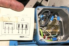
 Star-Delta traditional motor starting method used in practice (photo credit: teslacomponents.com.au)
The high starting currents often lead to unwelcome voltage drops in the supply network and the high starting torque put the mechanical elements under considerable strain.
With regard to mechanics, methods are required which reduce starting torque. Various starters and methods can be used to reduce currents and torque, but in the following passages, only traditional star-delta method used in practice is explained further.
A difference is made between:
- Normal Star-Delta Starters
- Enhanced Star-Delta Starters
- Star-Delta Starters with uninterrupted switchover (closed transition)
1. Normal star-delta starters
To enable the motor to start, the motor windings are configured in a star formation to the supply voltage. The voltage applied to the individual motor windings is therefore reduced by a factor of 1/√3 = 0.58 this connection amounts to approximately 30% of the delta values.
Due to the reduced starting torque, the star-delta-connection is suitable for drives with a high inertia mass but a resistance torque which is low or only increases with increased speed. It is preferably used for applications where the drive is only put under a load after run-up, i.e. for presses, centrifuges, pumps, ventilators, etc.

Where:
- I – Motor current
- Ie – Rated operating current of motor
- MΔ – Torque for delta connection
- ME – Rated operating torque of motor
- n – Speed
- ns – Synchronous speed
- ML – Load torque
- IY – Current in star connection
- IΔ – Current in delta connection
- IA – Current curve for star-delta start
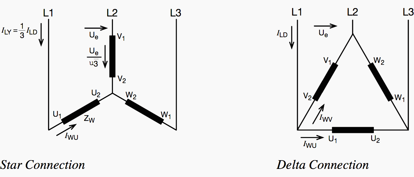
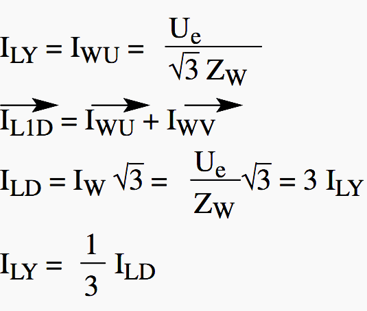
Current ratios for star and delta connections:
- ILY – Supply current for star connection
- ILD – Supply current for delta connection
- IW – Winding current
- Ue – Mains voltage between lines
- ZW – Winding impedance
After motor run-up, in most cases an automatic timing relay controls the switch-over from star to delta. The run-up using star connection should last until the motor has reached the approximate operational speed, so that after switching to delta, as little post- acceleration as possible is required.
Post-acceleration in delta connection will instigate high currents as seen with direct-on-line starting.
The duration of start in star connection depends on the motor load. During delta connection, the full mains voltage is applied to the motor windings.
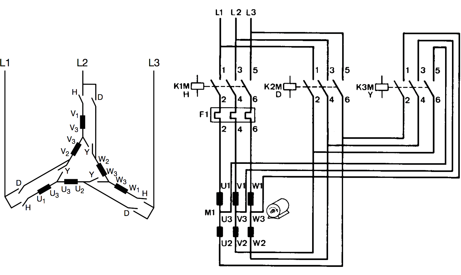
To enable a switch-over from star to delta, the six ends of the motor winding are connected onto terminals. The contactors of a star-delta starter switch over the windings accordingly.
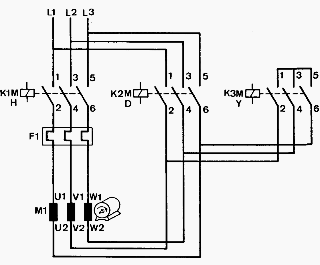
Starting in star, the main contactor connects the mains to winding endings U1, V1, W1. The star contactor shorts winding endings U2, V2, W2. After successful run-up, the star contactor switches itself off and the delta contactor connects terminals U1/V2, V1/W2, W1/U2.
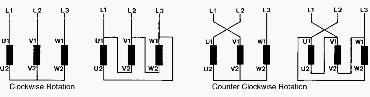
Incorrect phase sequence can lead to very high current peaks during the cold switch-over pause, due to the easy torque reduction following re-start. These peaks can damage the motor windings and stress the controlgear unnecessarily. The rotation of the motor has to be considered as well.
A sufficient time period has to be maintained between the star contactor’s de- energisation and the energisation of the delta contactor, in order to safely extinguish the star contactor’s disconnecting arc before the delta contactor is energised. During a switch-over which is too fast, a short circuit may develop via the disconnecting arc.
The switch over time period, however, should be just long enough for an arc disconnection, so that the speed decreases as little as possible. Special timing relays for a star-delta switch over fulfil these requirements.
Motor Protection and Contactor Sizing
The overload relay is situated in the motor line. Therefore, the current to be adjusted is lower than the motor’s rated current by a factor of 1/√3 = 0.58. Due to the third harmonics currents circulating in the motor windings, a higher setting of the overload relay may be required. This may only be carried out on the basis of utilising a measuring device which records the correct r.m.s. value.
For motor protection by means of power circuit breakers with motor protection characteristics (learn more), the power circuit breaker is switched into the network supply lines, as it also carries out short circuit protection of starter and lines. In this case, the current is set to the rated motor current. A correction of the set value because of the third harmonics is irrelevant under these circumstances. The lines are to be thermally proportioned depending on the power circuit breakers setting.
For normal star-delta starting, the controlgear must be sized in accordance with the following currents:
- Main contactor K1M 0.58 Ie
- Delta contactor K2M 0.58 Ie
- Star contactor K3M 0.34 Ie
For starting times exceeding approximately 15 seconds, a bigger star contactor has to be selected. If the star contactor is equal to the main contactor, start times of up to approximately one minute are permissible.
Go back to Star-Delta starting methods ↑
2. Enhanced star-delta starting
If the torque during normal star-delta starting is insufficient to accelerate the drive in delta connection to the approximate operational speed, then the enhanced star-delta start is utilised. With an increased torque, however, the current consumption during start-up also increases.
A difference is made between:
- Combined star-delta starting
- Partially wound star-delta starting
Both types require motors with accordingly tapped windings. The same guidelines for normal star connected starters apply to motor connection, contactor operation, motor protection and thermal conductor sizing.
2.1 Combined star-delta starters
In this case, the motor windings are usually divided into two equal halves. During start, half a winding is switched in delta, the other half in star. Therefore, the term “combined” is used. The star starting current is approximately 2…4 Ie.
This results in a correspondingly higher starting torque.
Sizing of controlgear:
- Main contactor K1M 0.58 Ie
- Delta contactor K2M 0.58 Ie
- Star contactor K3M 0.34 Ie
2.2 Partially wound star-delta starting
In this case, the motor windings are also subdivided. During star connection only the main winding, i.e. a part of the entire winding, is used. Therefore, the term “partially wound” is used.
The star starting current – depending on the tapping – amounts to 2…4 Ie, which also results in a higher starting torque.

Sizing of Controlgear:
- Main contactor K1M 0.58 Ie
- Delta contactor K2M 0.58 Ie
- Star contactor K3M 0.5 – 0.58 Ie (depending on starting current)
3. Uninterrupted star-delta starting
This connection prevents a drop in the motor speed during the switch-over from star to delta, and therefore, the following current peak is kept low.
Afterwards, the delta contactor K2M creates the final switching status and throws off transition contactor K4M.

Sizing of Controlgear:
- Main contactor K1M 0.58 Ie
- Delta contactor K2M 0.58 Ie
- Star contactor K3M 0.58 Ie
- Transition contactor K4M typ. 0.27 Ie (depending on transition current)
- Transition resistors typ. 0.35…0.4 Ue/Ie
The same guidelines for normal star connected starters apply to motor connection, contactor operation (connection differs due to activation of transition contactors), motor protection and thermal conductor sizing.
Go back to Star-Delta starting methods ↑
Reference // Basics for practical operation Motor starting by Rockwell Automation
Related electrical guides & articles


Edvard Csanyi
Hi, I'm an electrical engineer, programmer and founder of EEP - Electrical Engineering Portal. I worked twelve years at Schneider Electric in the position of technical support for low- and medium-voltage projects and the design of busbar trunking systems.I'm highly specialized in the design of LV/MV switchgear and low-voltage, high-power busbar trunking (<6300A) in substations, commercial buildings and industry facilities. I'm also a professional in AutoCAD programming.
Profile: Edvard Csanyi

Thank you very much for your efforts and good useful information you provide for us.
I really appreciated so much.
Best regards
Salem
Great article!
Hi,
The article was very helpful. Thanks.
Regards,
Chethan S