
Low voltage switching devices
This technical article will try to shed some light on switching devices usually installed in low voltage switchgear – circuit breakers, contactors, disconnectors, load-break switches, switch disconnectors and fuses. There are many variations of these devices, but the core function is the same – to protect, disconnect, or isolate.
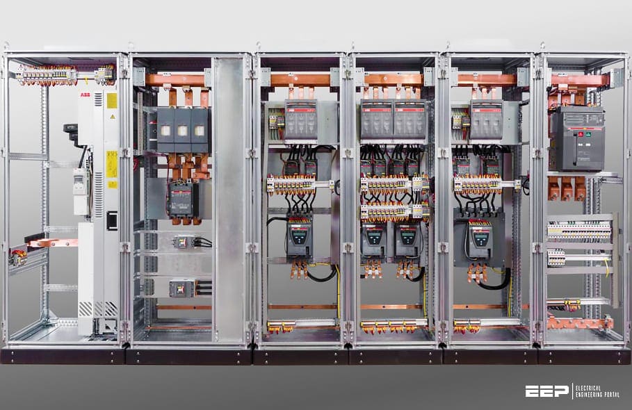 Five switching devices you are likely to spot in a low voltage switchgear
Low voltage switchgear is designed for switching and protection of electrical equipment. The selection of switching devices is based on the specific switching task, e.g. isolation, load switching, short-circuit current breaking, motor switching, protection against overcurrent and personnel hazard.
Depending on the type, switching devices can be used for single or multiple switching tasks. Switching tasks can also be conducted by a combination of several switchgear units.
Devices for up to 690 V, for example, have a test level of 1890 V for the rated insulation voltage. The rated impulse withstand voltage Uimp (stated on the switch or noted in the manufacturer’s documentation) for service in power distribution is as a rule 6 kV (IEC 60947-1, Table H1).
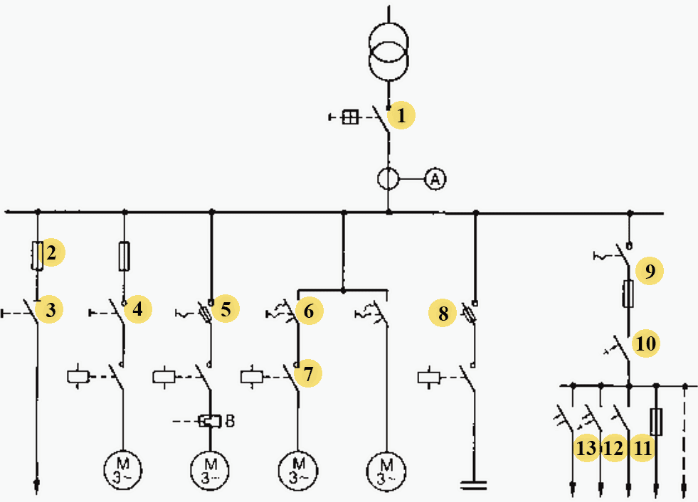
Figure 1 shows the applications of various switching devices.
Where:
- Circuit-breaker,
- Fuse,
- Disconnector,
- Load-break switch,
- Fused switch-disconnector,
- Motor starter (motor protection switch),
- Contactor,
- Overload relay,
- Switch-disconnector with fuses,
- Residual current-operated circuit-breaker (RCCB),
- Miniature circuit-breaker,
- Residual current-operated circuit-breaker with overcurrent hipping (RCBO),
- Residual current-operated miniature circuit-breaker (RCD)
When constructing low voltage installations it must be ensured that no higher voltages than the rated insulation voltages of the devices can occur.
- Circuit breakers
- Contactors
- Motor starters
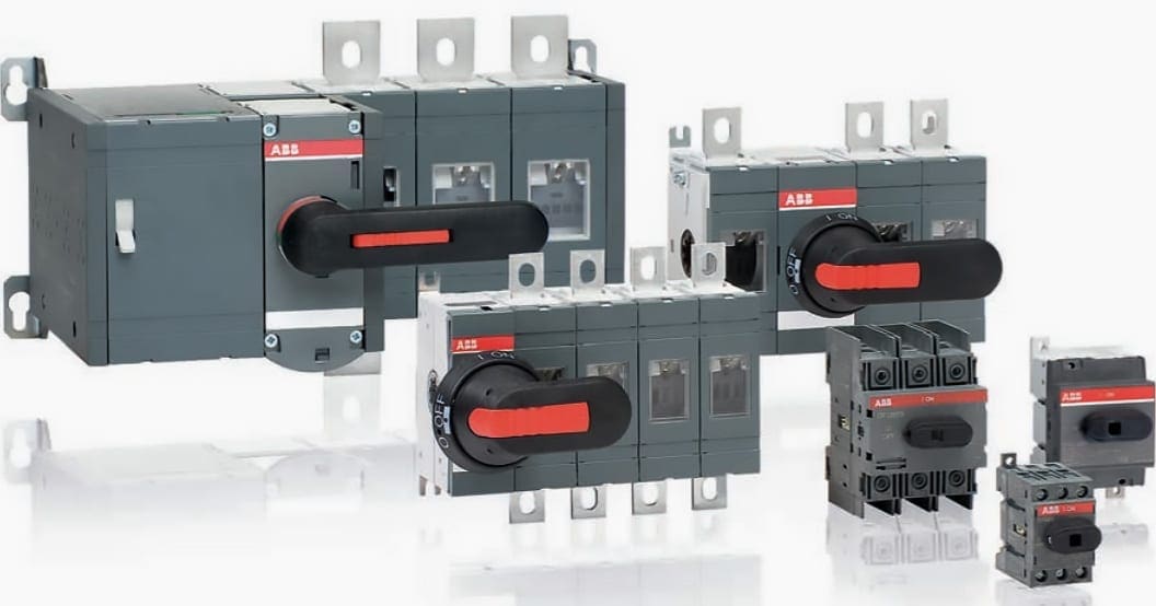
- Disconnectors, load-break switches and switch disconnectors
- Fuses
1. Circuit breakers
Circuit-breakers are defined in IEC 60947-2. Circuit-breakers most be capable of making, conducting and switching off currents under operational conditions. Furthermore, they must trip in accordance with defined current/time characteristics under overload and short-circuit conditions.
Circuit-breakers are used in applications with a low switching frequency. Circuit-breakers without overcurrent releases are known as switch-disconnectors.
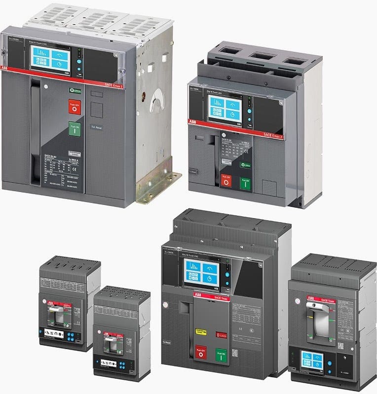
The basic classification criteria for low voltage circuit-breakers are the design (compact or open) and the quenching principle (non-current limiting or current limiting).
They are available for rated currents of up to 6300 A. The rated short-time current lc, is up to 100 kA.
Non-current limiting circuit-breakers quench the switching arc at the natural alternating current zero. The conductors are designed with a thermal capability allowing them to conduct the full short-circuit current.
All system components downstream are also subjected thermally and dynamically to the unlimited peak short-circuit current.
Current limiting circuit-breakers limit the short-circuit current before the peak of the first half-wave is reached. Limitation of the peak value significantly reduces the dynamic and thermal stresses on the connected system.
Figure 3 shows a diagram of the development of the unlimited (prospective) short-circuit current and the short-circuit current limited by the switching device. Limitation of the short-circuit current is achieved by extremely rapid contact separation and a sudden prolongation of the breaking arc.
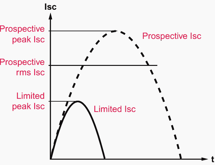
Current limiting circuit-breakers are particularly suitable for short-circuit protection of switchgear with a relatively low switching capacity (back-up protection).
Figure 4 shows the effects on the peak value to of the let-through current when a current limiting circuit-breaker is used (curve 2) in comparison with a non-current limiting circuit-breaker (curve 1), each in relation to the rms value of the rated short-circuit current.
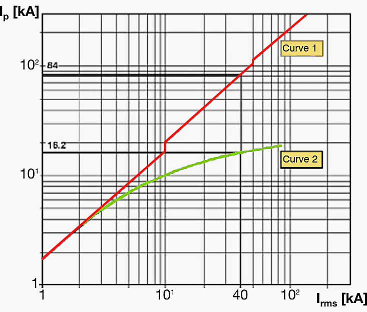
At an assumed rms current Irms of 40 kA, the peak level Ip with a non-current limiting circuit-breaker is 84 kA. The current limiting circuit-breaker however only permits a peak level of 16.2 kA, which significantly reduces the dynamic stresses on downstream system components.
Selection of circuit-breakers is first based on the rated voltage Ue, the rated current and the rated short-circuit breaking capacity. A distinction is made between two values for rated short-circuit breaking capacity:
- The rated service short-circuit current Ics (test sequence 0 — t — CO — t — CO) and
- The rated ultimate short-circuit current Icu (test sequence 0 — t — CO),
where:
- CO is a close/open operation, and
- t is the dead time between switching operations (3 min).
The rated short-time current lcw the utilization category, the ambient temperature and the installation conditions are then to be taken into account. The rated short-time current lcw is a peak value which is stipulated in accordance with Table 1, but which does not fundamentally provide any new information.
The utilization category classifies the breaker’s design-related characteristics with regard to selectivity. The distinction is made between:
- Utilization category A (circuit-breakers which are not specially designed for selectivity, e.g. current limiting circuit-breakers) and
- Utilization category B (circuit-breakers which are specially designed for selectivity).
Table 1 – Ratio n between short-circuit making and breaking capacity and the corresponding power factor (for AC voltage circuit-breakers) to IEC 60947-2
| Short circuit breaking capacity Icu | cosφ | Icm=n × Icu |
| 6 kA < Icu ≤ 10 kA | 0.5 | 1.7 × Icu |
| 10 kA < Icu ≤ 20 kA | 0.3 | 2 × Icu |
| 20 kA < Icu ≤ 50 kA | 0.25 | 2.1 × Icu |
| 50 kA ≤ Icu | 0.2 | 2.2 × Icu |
A fundamental factor in project planning is the selection of the protection release, which generally may have up to 4 protection functions:
- L – Overload, with settings for trip threshold (current) and inverse time delay.
- S – Selective short-circuit protection, with settings for trip threshold and delay time with constant energy or definite time characteristic.
- I – Instantaneous short-circuit protection, with setting for trip threshold.
- G – Earth fault protection, with settings for trip and inverse time delay with constant energy or definite time characteristic.
Circuit-breakers can also be equipped with residual current releases, making it possible to implement operator protection. Against direct and indirect contact and protection against fire.
Residual current protection devices are fundamentally distinguished by their design (add-on electronics unit with integrated instrument transformer or separate electronics unit (e.g. for door installation) and separate instrument transformer), by their response current (a.c. fault current, pulsating d.c. fault current, d.c. fault current) and their delay characteristics (selective or non-selective).
Go back to Table of Contents ↑
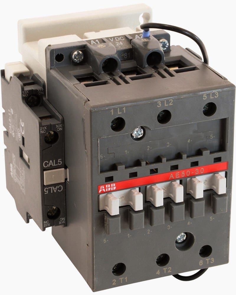
2. Contactors
Electromagnetic contactors are defined in IEC 60947-4-1. They are mechanical switching devices with only one position of rest, which are not operated manually and are capable of connecting, conducting and disconnecting currents in the circuit under service conditions, including operational overload.
They are especially suitable for high switching frequencies. Contactors are suitable for switching in accordance with the utilization categories described below. Protection against short-circuits is to be ensured by upstream protection equipment (SCPDs).
Apart from the electromagnetic actuation most often used, there are also contactors with pneumatic or electropneumatic actuation. For contactors and control devices on a semiconductor basis, IEC 60947-4-2 covers motor current circuits, and IEC 60947-4-3 covers non-motor loads with a.c. voltage.
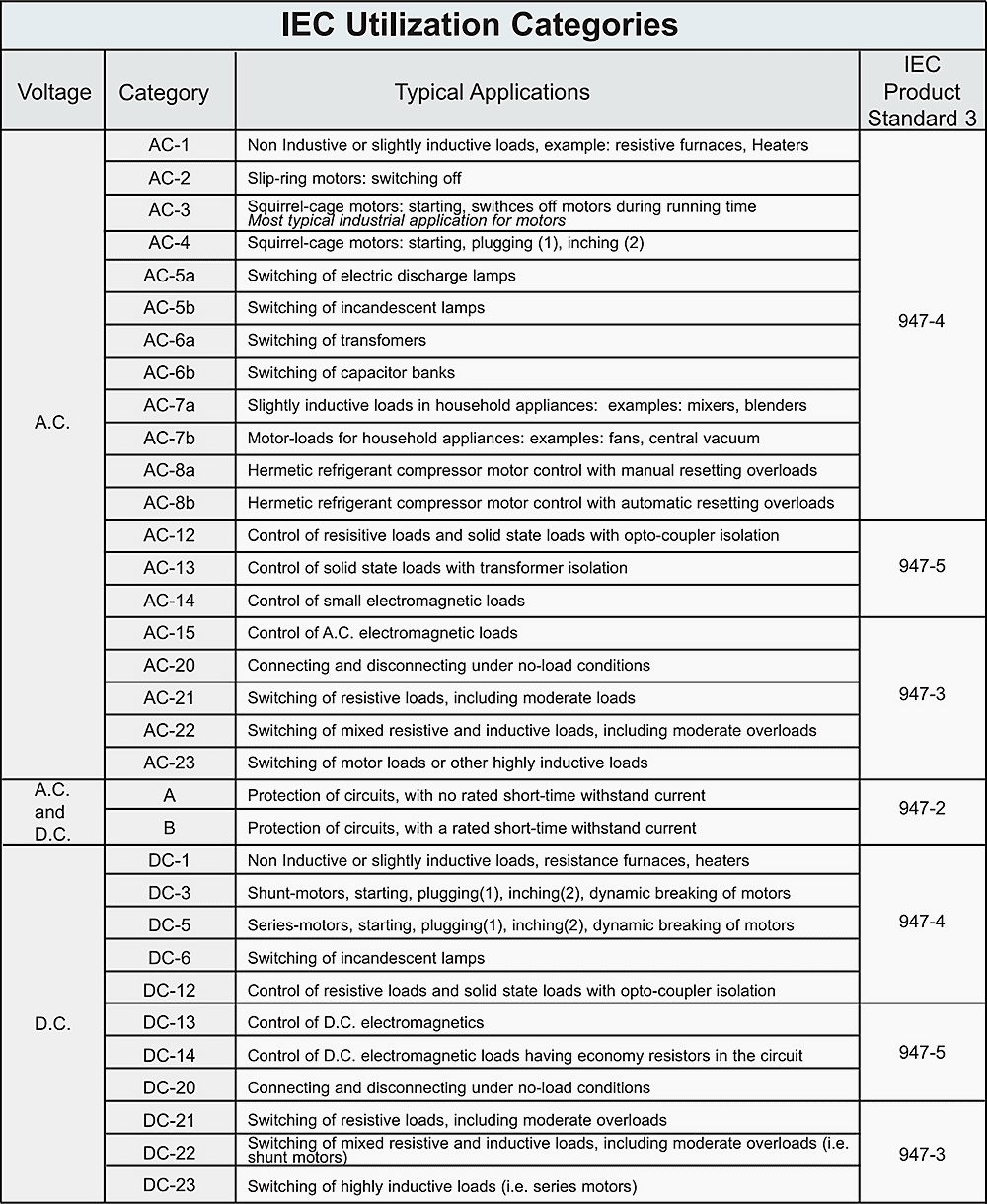
Contactors are selected by utilization categories, as shown in Table 2. In addition, the ratings (voltage, current, ambient temperature and control voltage) are to be considered. Background conditions such as switching frequency, number of poles, type of coordination, short-circuit level, start-up conditions and contact life are also to be taken into account.
The auxiliary contacts of contactors are „positively driven” in accordance with IEC 60947-5-1. NC auxiliary contacts in the contactors are „mirror contacts“, i.e. they cannot be closed at the same time as the NO main contacts. The positive driving and mirror property are essential in the implementation of safety circuits.
Table 2 – Utilization categories for contactors to IEC 60947-4-1
Go back to Table of Contents ↑
3. Motor starters
Motor starters based on electromechanical switching devices are also defined in IEC 60947-4-1. Accordingly, motor starters (Figure 7) are used to start motors, accelerate them to normal speed, ensure motor operation, disconnect the motor from the power supply and, by means of suitable protection systems, protect the motor and the corresponding circuit in the case of overload.
The starter may function as a direct-on-line starter (DOL), reversing starter (REV), star-delta starter (YD), heavy starter (HD) or soft starter.
As motor starters are as a rule used on the power distribution level, the components most be designed for a rated impulse withstand voltage Uimp of 6 kV.
The protection requirements play a decisive role in the design of a motor starter (Figure 8).
Overload relays detect overloading of the motor or the failure of a phase, and then act on the contactor to switch the motor off. There are both thermal and electronic overload relays, with various tripping classes (e.g. Class 10 or Class 30) for normal starting or heavy starting of the motor.
For direct online starting the overload relay is set to the rated service current of the motor (le), and for star-delta starting to 0.58 × le.
Circuit-breaker to IEC 60947-2 and 60947-4-1 with short-circuit and overload releases for protection of motors:
Go back to Table of Contents ↑
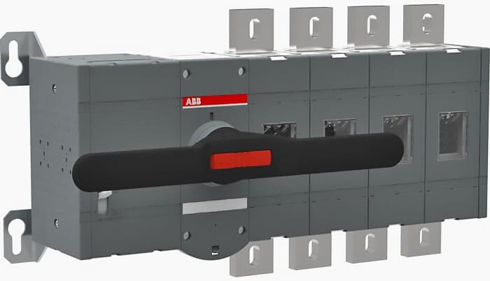
4. Disconnectors, load-break switches and switch disconnectors
The requirements for mechanical switching devices for switching of load currents and safe isolation of systems or subsystems from the supply network are the subject of standard IEC 60947-3.
Disconnector
The isolating function of the disconnector in the open position is characterized by the following features:
- Increased dielectric strength of the contact gap (demonstrated by a test at impulse voltage)
- Low leakage current across the isolating distance Clear indication of the OFF position of the contacts
- No inadvertent closing (e.g. by vibration) Facilities for actions to prevent impermissible reclosing
A disconnector can only open and close a circuit if either a current of negligible quantity is switched off or on, or if there is no significant voltage difference between the two contacts of each pole.
Load-break switch
A load-break switch can, under normal conditions in the circuit, if applicable with specified overload conditions, make, conduct and break currents and, under specified abnormal conditions such as a short-circuit, conduct these short-circuit currents for a specified period.
Switch-disconnector
A switch-disconnector is a load-break switch that meets the requirements specified for an isolating distance in the open position.
Switch-disconnector with fuses
Unit comprising switch-disconnector and fuses, in which one fuse is connected in series with the switch-disconnector in one or more phases. Fuse switch-disconnector
A fuse switch-disconnector is a switch-disconnector in which a fuse link or a fuse holder with fuse link forms the movable contact.
Switching mechanisms
- Dependent manual actuation: Actuation exclusively by human effort, so speed and power for the switching movement depend on the operator.
- Independent manual actuation: Actuation by a stored-energy mechanism, in which the energy applied manually is stored as tension and released during the operating motion, so speed and power for the contact movement are independent of the operator.
- Stored-energy operation: Actuation by energy stored in the actuating mechanism, which is sufficient to complete the switching operation under specific conditions.
The energy is stored before the actuation begins. Stored-energy mechanisms are differentiated by the type of:
- Energy storage (spring, weight etc.),
- Energy source (manual, electric motor etc.),
- Energy release (manual, release coils etc.).
Go back to Table of Contents ↑
5. Fuses
Low voltage fuses are defined in accordance with IEC 60269-1. Fuses are protective devices which open a circuit when one or more fuse elements blow and interrupt the current when it exceeds a given level for a specified duration.
The application ranges of fuses are identified by two letters. The first letter identifies the breaking range:
- g — General purpose fuse links
These can continuously conduct currents up to their rated current and can interrupt currents from the smallest fusing current to the rated breaking capacity. - a — Back-up fuse links
These can continuously conduct currents up to their rated current and can interrupt only currents above a specific multiple of their rated current.
The second letter identifies the application, i.e. the time-current characteristic:
- G — for general application
- M — for the protection of motor circuits and switching devices
- R — for protection of semiconductor components
- Tr — transformer protection
- B — mine substation protection
- D — fuse links with delay North American
- N — fuse links without delay practice
Go back to Table of Contents ↑
Sources:
- ABB pocket book 10th edition
- Electrical installation guide 2016 by Schneider Electric
- Electric distribution systems by Abdelhay A. Sallam and Om P. Malik
Edvard Csanyi
Hi, I'm an electrical engineer, programmer and founder of EEP - Electrical Engineering Portal. I worked twelve years at Schneider Electric in the position of technical support for low- and medium-voltage projects and the design of busbar trunking systems.I'm highly specialized in the design of LV/MV switchgear and low-voltage, high-power busbar trunking (<6300A) in substations, commercial buildings and industry facilities. I'm also a professional in AutoCAD programming.
Profile: Edvard Csanyi

Very excellent article MV and LV switching devices with practical applications and with device pictures.
Thank you very much for sharing!
You’re welcome, Carl. I’m glad you find this artice useful.
very useful article, hopes future also share such article
It was really very useful article and I also need to Standard Operation Procedures Sop for HV substations. Can anyone help me in this regard?
Thank you for sharing your experience…. Really Great Article.
Thank you
thanks for sharing your experience and video, for me you learn something new. Regards.
EEP seems to be very helpful to me. This is my second day with EEP! Last time I saw the tests to be conducted for Transformers.
I would like to be a regular member of EEP. My utmost thanks to Mr. EDVARD CSANYI, the founder of EEP for his excellent assertion in the arena of the Electrical engineering portal.
Regards
Mostafa Kamal
4 August 2020, Dhaka, Bangladesh
The use of FSU switch gear for the Protection of DC circuits – now with the use of solar panels there is a lot of confusion for protection of higher current arrays etc a series of articles
in regard to this would be appreciated.
Dear Edward,
Thank you very much for publishing such a valuable article on Switching Devices in Low Voltage Switch gear.
You are welcome Jagadish, I’m very glad you find it useful.
Studying hard and as well working hard leads to improvement in your work
A very useful information!
Keep the work up
Article is informative…. how to download the pdf of the article
Would like to know about earting and primary/secondary protection.
Your notifications are quite helpful. Keep it up.
I want to learn Autocad programming and other automation software
Thanks, your publications it’s very good for me!!!