The purpose of switching impulse test
The switching impulse test is applied to confirm the withstand of the transformer’s insulation against excessive voltages occurring during switching. During the switching impulse voltage test, the insulation between windings and between winding and earth and withstand between different terminals is checked.

The purpose of the switching impulse test as the special test is to secure that the insulations between windings, between windings and earth, between line terminals and earth, and between different terminals withstand the switching overvoltages, which may occur in service.
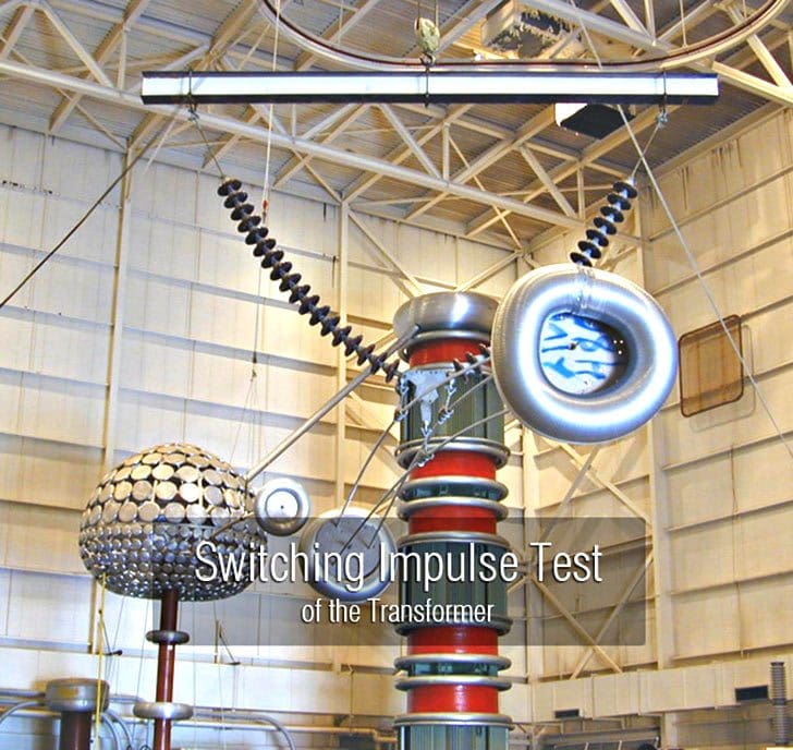
The switching impulse voltage is generated in conventional impulse voltage generators at the laboratories.
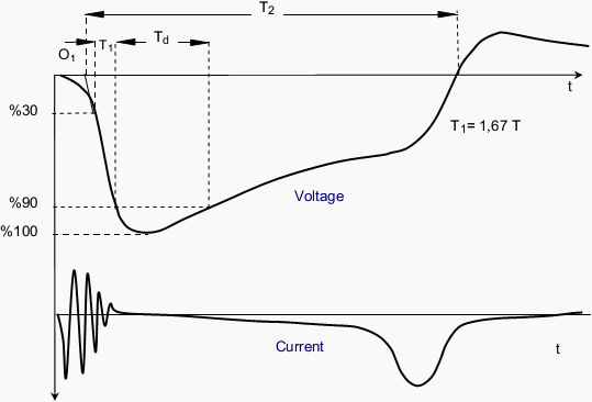
The polarity of the voltage is negative and the voltage waveform should normally be T1/ Td/ T2 20/200/500 μS (figure 2) according to IEC 60076-3.
Due to over-saturation of the core during the switching impulse test, a few low amplitudes, reverse polarity (e.g. positive) impulses are applied after each test impulse in order to reset the transformer core to its starting condition (demagnetized). In this way, the next impulse voltage waveform is applied. The tap position of the transformer during the test is determined according to test conditions.
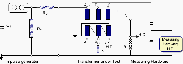
The on-off impulse voltages are applied to each high voltage terminal sequentially.

Meanwhile, the neutral terminal is earthed. The windings which are not under test are left open (earthed at one point). This connection is similar to the induced voltage test connection. The voltage distribution on the winding is linear like the induced voltage test and the voltage amplitudes at the un-impulsed windings are induced according to the turn ratio.
Meanwhile, necessary arrangements should be made since the voltage between phases will be 1,5 times the phase-neutral voltage.
The change of the voltage waveform and winding current are measured with a special measuring instrument and recorded. The negativities in the transformer during the test are determined by comparing the voltage and current oscillograms.

The sudden collapses of the voltage (surges) and abnormal sounds show the deformation of the insulation in the transformer. The deformation of the voltage waveform and increase in noise due to magnetic saturation of the core should not be considered as a fault.
The test voltage values, impulse shapes, and a number of impulses at different voltage levels must be stated in the report.
Switching Impulse Voltage Waveform :
Front : T1 ≥100 µS = 1,67 T
90% value : Td ≥ 200 µS
Time for cutting the axis: T2 ≥ 500 µS
Resource: Transformer tests – BALIKESİR ELEKTROMEKANİK SANAYİTESİSLERİA.Ş.


From which voltage, switching impulse test is applicable?
thank you very much . it was clear
Hi Sir,
Currently,I have 1 pcs of Impluse Transformer that need your help to cross equipvelent.Pls kindly advise if your e mail address.
Keves Csanyi kollega !
Ha a masik ket tekercset rovidre zarja es a transformer 3 oszlopos a merendo tekercs impedanciaja
alacsony lesz,, rovid” tail time ”
Kulonben is ” switching surge ” a tekercsek egymastol valo szigetelesenek ellenorzesere van,
nem pedig a menetek kozotti szigetelest vizsgalni.
Hivjon telefonon 201 748 7731