
Accurately Measuring Earth Resistance
Large ground systems, such as those found in substations and power stations, are an important part of the protection of the electricity supply network. They ensure that fault current will enable protective devices to operate correctly.
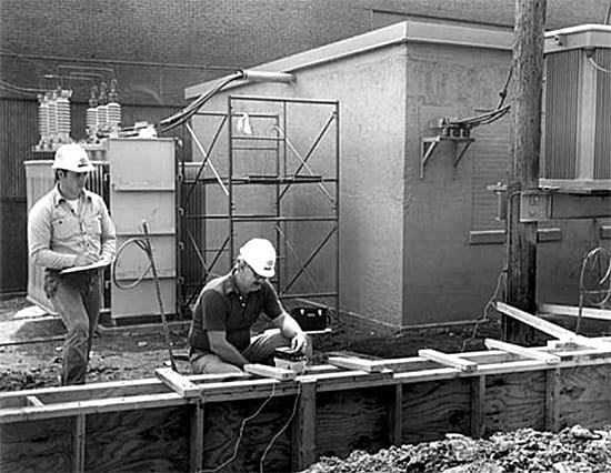
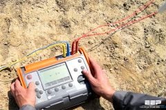
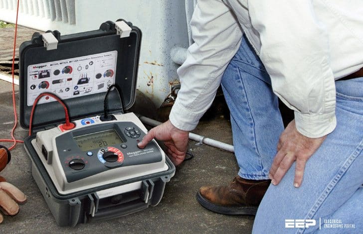 Testing Challenges in Large Ground Systems (photo credit: blog.jmtestsystems.com)
A substation must have a low ground resistance to reduce excessive voltages developing during a fault which could endanger safety of nearby people or damage equipment.
When installing a ground system the resistivity of the surrounding soil should be measured. Inaccurate resistivity tests can lead to unnecessary costs in the design of the system.
After installation it is vital to check that the electrical grounding system meets the design criteria and should be measured periodically to ensure corrosion or changes in the soil’s resistivity do not have an adverse effect. Ground networks may not appear faulty until a fault occurs and a dangerous situation arises.
Suitable test techniques must be used for large systems to ensure that valid readings are obtained. This is unlike a small single ground rod (for example, a lightning protection system or residential ground) which can be simple to test.
Testing Challenges in Large Ground Systems
Securing valid measurements when testing large ground systems requires that proper techniques and instrumentation be used. The nature of substation and power station grounding systems and related conditions make testing far more complex than on a simple ground rod.
Following are the three key challenges in testing substation ground systems //
1 // The physically large area of a substation/power station ground system results in a large “resistance area” and, consequently, long distances to the test probes; ideally, the current test probe should be placed 10 times the maximum distance on the ground system (e.g., 3000 ft for a 300 ft2 ground grid) to find the “flat” portion of the characteristic resistance curve.
2 // The large “resistance area” typically gives ground resistance values of less than 0.5 Ω. Test instrument resolution is critical if small variances in readings are to be observed.
If the test instrument does not have suitable resolution, instrument errors can overwhelm the results.
3 // Large electrical networks contain noise consisting of the frequency of the power utility and its harmonics, plus high frequency noise from switching, etc., and induced signals from other sources. The ground tester must retrieve and analyze a small test signal in a much larger test environment.
Most ground testers only inject a single frequency (usually 128 Hz) which is adequate in most situations because it avoids harmonics of standard line frequencies. Unfortunately, it is often not adequate in substations. This type of interference can cause significant measurement errors.
Addressing the Testing Challenges in Large Ground Systems
In the ideal world, testing a large ground system would be conducted in complete accordance with the Fall-of Potential Method. Unfortunately, the large “resistance areas” found in large ground systems may make it unfeasible or even impossible to carry out this test.
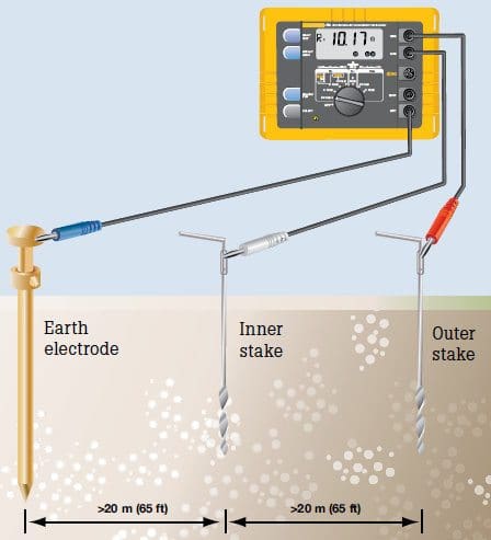
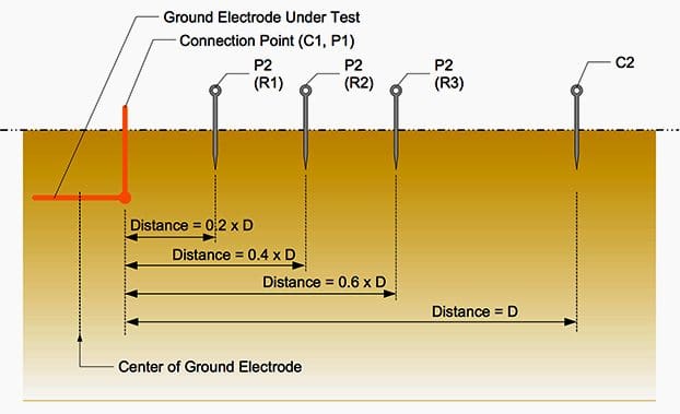
As noted above, setting the current test probe 10 times the maximum distance of the ground system can require leads to be many thousands of feet. In these situations, the Slope Method can be used effectively because it does not require the user to find the “flat” portion of the curve or to know the electrical center as a point from which to measure.
Readings are taken at 20 percent, 40 percent and 60 percent of the current probe distance and fit into a mathematical model of the resistance characteristic.
For the Slope Method to provide meaningful results, accurate measurement of the variations at different points is critical. Since large ground systems typically have resistance values of less than 0.5 Ω, the differences can be quite small. An instrument with 1 mΩ measurement resolution can indicate the small differences between low readings.
Noise is a major problem in testing large ground systems, and must be addressed to ensure accurate results. To be effective, the test instrument must be designed to overcome the effects of significant noise in the test environment.
Among the technical capabilities that can help offset the noise problem are:
- A variable test frequency (rather than a single, fixed test frequency) which can help remove any stray noise that could affect the reading.
- A high peak-to-peak interference suppression level.
- A sophisticated filter system to reject more noise.
- Various current settings to improve the signal-to-noise ratio when necessary.
Reference // Getting Down To Earth – MEGGER (Download guide)
Related electrical guides & articles


Edvard Csanyi
Hi, I'm an electrical engineer, programmer and founder of EEP - Electrical Engineering Portal. I worked twelve years at Schneider Electric in the position of technical support for low- and medium-voltage projects and the design of busbar trunking systems.I'm highly specialized in the design of LV/MV switchgear and low-voltage, high-power busbar trunking (<6300A) in substations, commercial buildings and industry facilities. I'm also a professional in AutoCAD programming.
Profile: Edvard Csanyi

The problem is that they are using instruments that injected currents of milli amps which are very limited for these large cases of substations. You must use high current (1 to 10A) and take the measurement. It is insufficient to use instruments without power. In addition, the precision of these small teams according to their own catalogs is + /- 10 % what doesn’t make any guarantees for more sensitivity than have
well all i want to say to you is ” Thanks a lot ” for being number one in my list .
special thanks to the author