
Estimated Study Time: 4 minutes
Content:
- Equipment required for testing
- General inspection
- Insulation Resistance Test
- Polarity Test
- Transformer Turns ratio test
1. Equipment required
Following equipment is necessary to perform testings:
- Polarity test kit
- Megger 500-5000V
- Ohmmeter
- Multimeter
- Autotransformers & Step-up transformers
2. General inspection
Mechanical checks
- General visual inspection and compliance with the drawings and manuals.
- Check nameplate ratings and HV, LV terminal markings.
- Check that all parts of the transformer are properly assembled and tight.
- Check the HV connections are tight.
- Check the cable connections on the LV side and the markings.
- Check the oil levels and inspect for leakage. (Where applicable)
Capacitor dividers type
Check that all parts of the transformers are properly assembled.
Electromagnetic type
Check the installation of different sections.
Electrical Checks
- Check the equipment grounding (Continuity and connection)
- Check the fuse rating of secondary side.
- Perform the operation described in the following
Insulation Resistance Test
To obtain values as close as possible to the manufacturer’s specifications the insulators must be very clean. Select the megger range corresponding to the ratings of the equipment under test.
For Primary side, apply voltage depending on rating of voltage rating of VT.
- For 6.6 kV VT (example), apply 2.5 kV and
- For 132 kV VT (example), apply 5.0 kV.
Polarity Test
The polarity is checked using the flick method (application of direct current) and check of deflection on a bi-directional milliammeter. The test is also used to check primary and secondary circuit continuity.
- When switch k is closed, the milliammeter pointer deflects positive.
- When the circuit is opened, the milliammeter pointer deflects in the negative direction.
Transformer Turns ratio test
A variable AC source is applied on the primary side. The primary and secondary voltages are measured to determine the ratio V2/V1
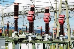
132kv Substation
Reference: Contract specific procedure for testing of electrical equipment and 132kV OHL
Related electrical guides & articles


Edvard Csanyi
Hi, I'm an electrical engineer, programmer and founder of EEP - Electrical Engineering Portal. I worked twelve years at Schneider Electric in the position of technical support for low- and medium-voltage projects and the design of busbar trunking systems.I'm highly specialized in the design of LV/MV switchgear and low-voltage, high-power busbar trunking (<6300A) in substations, commercial buildings and industry facilities. I'm also a professional in AutoCAD programming.
Profile: Edvard Csanyi

Thanks.
THANKS FOR THIS INFORMATION
This presenation is good but not all the info is 100%.
For instance the identification of the VT Primary and secondary connections is wrong, Primary connections are labelled in Capital letters as A and N and secondary as a and n, your info might confuse first time students who wil perform these test.
Also when you perform the insulation tests you remove the Primary N connection from earth when you test from Primary to earth and dont connnect it to the secondary as well because you want individual readings for each test performed to prove that each core is insulated on its own accordingly.
the different secondary cores have different purposes and different VA’s , like for Metering and Protection purposes.
When you test a CTPT unit it has a earth link in the secondary connection box that you have to remove before you start with the insulation tests.
For the Polarity test 9 V or 12 V battery will be enough just make sure that the amp or Volt meter measures in mili amps( Volt), because due to the VT ratio you will get a miliamp or milivolt output.Use any quality galvano meter with a DC mili amp or volt selection to make your test easier.
For the ratio test you can at least inject from 500-1000 V across the primary connections and measure output on secondary, these were tests performed on 11 kV to 132kV VTS the error was still within the spec’s allowed.But the Accuracy class was then from 0.2Cl to 0.5Cl.
Long before the CT analyser or CPC 100 Voltano 100 Sverker 750/760 or 950 was build we used a self build injection set for mag curves that could inject max 1000 V and up to 5 amps that we used for Metering and Protection CT’s to do the mag curves and we used it for VT ratio test because it had enough VA to perform the tests.
Edvard sorry hat I used your blog here but in the Electrical field we share our info because and help others that are new to this field ours.
Regards
Francois
Dear Sir,
In the diag given for PT IR Measurement Sec- E Dont u think the sec S-2/S-2 Should be shorted & one end of the Pri i.e either P1 or P2 should be earthed & Megger should be connected between Shorted S-2 & earth ?
Thanks for sharing this useful article,
but it could be better if someone could also refer to respective IEC article about details of test, for example in ratio test of PT, how much should be primary connected voltage to PT primary winding, because error percentage is different in different levels of voltage, and IEC as a comprehensive reference for sure pointed that out, if any one has such IEC respective article, it would be appriciated in advance.for sharing it
Very good notes about article
The information is quite good. Thanks a lot.
isn’t any concept of knee point in voltage transformer ??
Thanks for the helpful tips on the subject and service to the community.
So many thanks ,sir
Edvard you r doin g8t job and appreciate from bottom of my heart. thanks alot
Really hats up..
Nice site author we are glad to u and thanx a lot
Helping Topic
Dear Mr.Edvard,
what is the votage rating of DC battery for polarity test and ratings of Auto transformer and Step down Transformer for Ratio test. Please replay as soon as.
Thanks
With Rgds
Shahed
Thank you, that was interesting
Thank you Mr. Edvard.
Where can i download the technical documents
See the blue button ‘Get PDF’ on your left? That’s your answer! Create PDF from any technical article and save it on your disc.
Topic is good but the contained matter is too short…explain with details & include balancing of transformers also…
AK