
Estimated Study Time: 11 minutes
Thermistor motor protection
Thermistor is a small non-linear resistance sensors, which can be embedded within the insulation of a motor winding, to provide a close thermal association with the winding. It’s made from a metal oxide or semiconductor material.
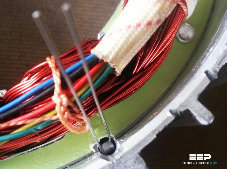 Practical tips for installation and using of motor thermistor protection (on photo: 10k NTC glass thermistor installed in electric motor; credit: endless-sphere.com)
The relationship between resistance and temperature is non-linear and the resistance varies strongly with small temperature changes around the set point.
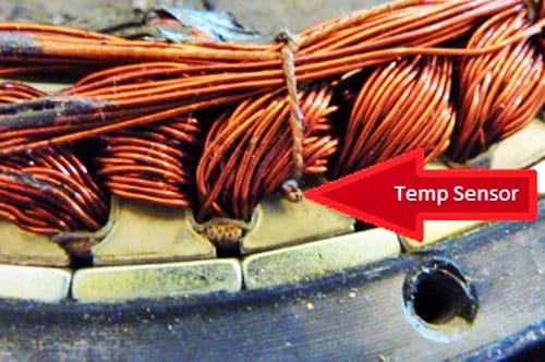
Thermistors are most easily inserted into the non-rotating parts of motors, such as the stator winding in an AC motor or the interpole and field windings of a DC motor.
4 thermistor advantages
The main advantages of thermistors are:
- Their small size allows them to be installed in direct contact with the stator winding.
- Their low thermal inertia gives rapid and accurate response to winding temperature changes.
- They measure temperature directly irrespective of how these temperatures are initiated.
- They can be used to detect overload conditions in motors driven by frequency converters.
The temperature coefficient can be positive (PTC – positive temperature coefficient), where the resistance increases withtemperature, or negative (NTC – negative temperature coefficient), where the resistance decreases with temperature.
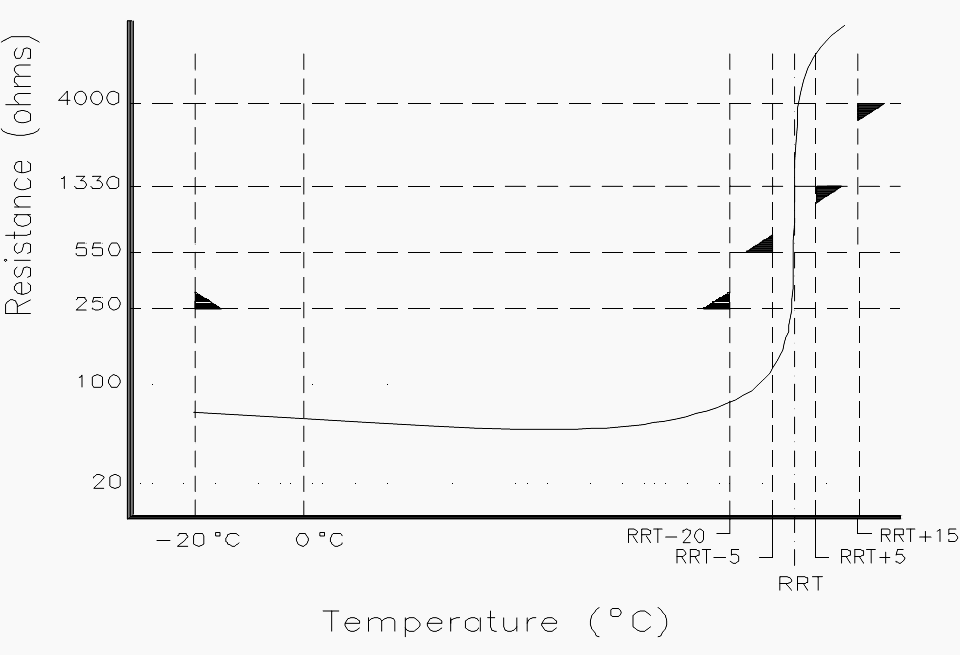
RRT is Rated response temperature. IEC specified temperature/resistance limits are clearly marked
The type most commonly used in industry is the PTC thermistor, whose typical resistance characteristic is shown in the curve above.
The resistance at normal temperatures is relatively low and remains nearly constant up to the rated response temperature (RRT). As the RRT is approached and exceeded, the gradient of the resistance increases sharply, giving the PTC thermistor a high sensitivity to small changes of temperature.
At the set point, a temperature rise of a few degrees results in a large increase in resistance. The resistance is monitored by a thermistor protection relay (TPR) and, when the sharp change in resistance is detected by the thermistor protection relay (TPR), it operates a contact to initiate an alarm or to trip the protected device.
Thermistor protection relays are required to trip reliably when the sensor resistance rises above about 3 kΩ.
They will also respond to an open circuit, either in the cable or the thermistor sensor, thus providing fail-safe protection. Modern TPRs are also designed to detect a thermistor sensor short circuit,when sensor resistance falls below about 50 Ω.

The specified operating levels are:
- Thermistor over-temperature protection according to IEC:
- Response level = 3300 Ω± 100 Ω
- Reset level = 1650 Ω± 100 Ω
- Thermistor short-circuit protection according to IEC:
- Response level ≤ 15 Ω
In DC motors, PTC thermistor sensors are increasingly used instead of microtherms, which are described in the section above. The rated response temperatures (RRT), which are commonly selected for the various classes of insulation on electric motors, are summarized in the table in Figure 3.
Figure 3 – Typical temperature level settings used on rotating electrical machines
| Insulation class | Rated temperature | Alarm temperature | Trip temperature |
| Class B | 120°C | 120°C | 130°C |
| Class F | 140°C | 140°C | 150°C |
| Class H | 165°C | 165°C | 175°C |
Due to the relatively slow transfer of heat to the sensors through the insulation medium, PTC thermistors do not provide sufficiently fast protection for short circuits in motors or transformers. Also, since they are usually located in the stator windings, they do not provide adequate protection for rotor critical motors or for high inertia starting or stalled rotor conditions.
The application of PTC thermistors as temperature sensors is only effective when:
- The rated response temperature (RRT) of the thermistor is correctly selected for the class of insulation used on the winding.
- The thermistors are correctly located close to the thermally critical areas.
- There is a low thermal resistance between the winding and the PTC thermistor. This depends on the electrical insulation between the winding and the thermistor. Since thermistors need to be isolated from high voltages, it is more difficult to achieve a low heat transfer resistance in HV motors, which have greater insulation thickness.
Several thermistor sensors may be connected in series in a single sensor circuit, provided that the total resistance at ambient temperatures does not exceed 1.5 kΩ. In practice, and as recommended by IEC, up to six thermistor sensors can be connected in series.
If the operator takes no action, the tripping group is used to trip the motor directly to prevent damage to the winding insulation.
In many cases, users choose both groups to have the same RRT. In this case, only one group of thermistors is used (one in each phase) and these are then used for tripping the motor. This provides for one spare thermistor in each phase.
The physical location of the thermistor sensors in an AC motor depends on the construction of the motor, whether it has a cylindrical rotor or salient pole rotor, and several other design and manufacturing variables. In some cases, the optimum location may have to be determined from test experience.

Thermistor protection relay
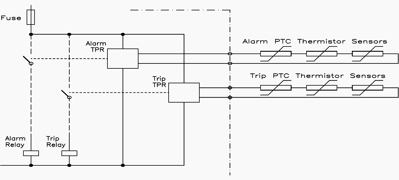
Thermistor protection relay (TPR) is designed for mounting inside a control cubicle or motor control center (MCC), usually on standard terminal rail. The Figure 6 shows a typical connection of two thermistor protection relays, and their associated groups of thermistor sensors.
For alarm and trip control of a 3-phase AC induction motor. The performance of thermistor protection relays can be affected by external electrical interference, where voltages can be induced into the sensor cable.
Consequently, cables between the thermistor protection relay and the PTC thermistor sensors should be selected and installed with a view to minimizing the effects of induced noise.
Cables should be kept as short as possible and should avoid running close to noisy or high voltage cables over long distances!
During testing, care should be taken not to megger across the thermistors as this can damage them!! The correct procedure is to connect all the thermistor leads together and to apply the test voltage between them and earth or the phases.
Some practical recommendations for the type of cables that should be used are as follows:
- Distances ≤ 20 m – Standard parallel cable is acceptable
- Distances ≥ 20 m, ≤100 m – Twisted pair cable is necessary
- Distances ≥ 100 m – Screened twisted pair (STP) cable is necessary
- High level of interference – Screened twisted pair (STP) cable is necessary
The screen should be earthed at one end only
For cable distances to the sensors of greater than 200 meters, the cross-sectional area of the conductors should also be considered. The following are recommended:
Figure 7 – Recommended cable size to thermistor sensors
| Conductor cross-section | Maximum length | Type of cable |
| 0.5 mm2 | 200 m | Screened twisted pair (screen earthed at one end only) |
| 0.75 mm2 | 300 m | Screened twisted pair (screen earthed at one end only) |
| 1.0 mm2 | 400 m | Screened twisted pair (screen earthed at one end only) |
| 1.5 mm2 | 600 m | Screened twisted pair (screen earthed at one end only) |
| 2.5 mm2 | 1000 m | Screened twisted pair (screen earthed at one end only) |
New generation of thermistor motor protection relays
Reference // Practical Variable Speed Drives and Power Electronics by Malcolm Barnes (Purchase paperback from Amazon)
Related electrical guides & articles


Edvard Csanyi
Hi, I'm an electrical engineer, programmer and founder of EEP - Electrical Engineering Portal. I worked twelve years at Schneider Electric in the position of technical support for low- and medium-voltage projects and the design of busbar trunking systems.I'm highly specialized in the design of LV/MV switchgear and low-voltage, high-power busbar trunking (<6300A) in substations, commercial buildings and industry facilities. I'm also a professional in AutoCAD programming.
Profile: Edvard Csanyi

Thank you for your efforts. Keep going. Live long.
How can I monitor the motor winding and bearing temps. on a continuous basis.? at a cheaper price. We have 14 numbers of 108 KW motors where I want to implement this.
Please give me the control video of how ptc is connected to an ac motor.
Hi, Can you advise which IEC section and clause?
Thanks .Great help !
I’ve a pad-lockable maintenance safety switch installed to power off the motor with integrated PTC. After lock-out the motor there is still power on the measurement signal of the PTC.
How can I handle this issue? Use an auxiliary contact to isolate off the power of the measurement module?
i have one set of motors (two motors -1A,1B) . Can I loop these two motors with one thermister relay? If i did like this what will happens ,it means advantages and disadvantages ,can u explain briefly ?
How the size of cables related to the operation of PTC,
For eg. What happens if the sensor is connected to the relay by using 6sq.mm copper cable, instead of 2.5sq.mm al. cable
What’s about PTC or RTD installed in motor suitable for classified area? We have to install a barrier in the MCC?
VERY GOOD ONE THANK YOU