Term “good power quality”
Most electrical and electronic equipment is designed to operate from a power supply with a particular specification that usually defines the minimum and maximum limits for RMS (root mean-square) voltage and frequency. There is an expectation on the part of the user that the supply will be available and within tolerance for 100% of the time. This is not guaranteed by the supplier and would be practically impossible to realize at an economic price level.

Electricity is unlike any other product in that quality cannot be assessed before delivery. It is used at the time of production but some distance away from the point of production having passed through several transformers, many miles of transmission lines and having been mixed with the output of other generators.
The term ‘good power quality’ can be used to describe a power supply that is always available, always within voltage and frequency tolerances, and has a pure noise-free sinusoidal wave shape. ‘Poor power quality’ describes any supply that deviates from this ideal; whether or not the deviation is important depends on the purpose of the installation, the design of the equipment and the design of the installation.
The major causes of poor power quality fall into two categories that are discussed in this article //
The separation between these categories is never complete because disturbances caused by equipment on one site may result in damage or disruption to equipment on another site. For example, a heavy load, such as an arc furnace, in a factory unit on a small estate may cause a voltage dip to several neighbouring users when it is switched on.
The result may be complete shutdown of a computer network causing disruption far greater than would be expected by the operator who pushed the button.
1. Supply system quality problems
Supply interruption
Complete loss of power lasting more than one minute. Caused by generation or distribution plant failure, transmission line faults, or load shedding during system overload. The obvious effect is complete shutdown of all electrical plant.

Transient interruption
Complete loss of power for less than one minute. Usually caused by auto-reclosers restoring power after transient faults. Computers and communications equipment will shut down with loss of data. Restart times may be several minutes: data recovery times will be much longer.
Transients
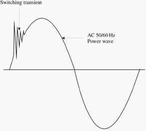
Fast rise-time high voltage pulses superimposed on the supply voltage. Can be caused by a number of factors, including the residual effects of lightning strikes, power factor correction capacitor switching and inductive load switching.

Under/over voltage
Long term excursion outside statutory limits. Caused by failure of tap changers. Under voltage (‘brownouts’) may be introduced deliberately by the supplier to reduce demand and can cause unreliable equipment operation, including repeated re-booting of computer systems, solenoid drop-out and overheating of squirrel cage motors. Over-voltage may cause permanent damage to a wide range of electrical and electronic equipment.
Voltage dip/surge
Short term voltage disturbance outside statutory limits. Caused by starting and shutting down heavy loads such as large motors. In extreme circumstances, dips can cause equipment shutdown and surges can cause equipment damage.
Voltage imbalance
Asymmetry of phase voltages of a three-phase supply. Caused by differential loading of phases. Results in circulating current (and excess heating) in transformers and reduced efficiency of three-phase motors.
Flicker
Periodic fluctuations in supply voltage. Caused by presence of cyclical load variations, e.g. from a cyclo-convertor drive system. Results in visible flicker in lighting systems.
Harmonic distortion
Distorted voltage waveform. Caused by non-linear loads. Causes overheating due to increased eddy and hysteresis loss in transformers, overheating and reduced torque in motors and overheating in neutral conductors and power factor correction capacitors.

Although classified as supply problems, sometimes the root cause may lie within the user’s own premises.
2. Installation and load related problems
There are three major installation related problems:
1. Harmonic current
Harmonic currents arise from the increasing prevalence of non-linear loads now in use and cause problems in cabling, transformers and motors. Drawing harmonic currents from the supply imposes distortion on the voltage waveform that, if unchecked, could cause problems
for other users of the supply and so limits are imposed on the permitted magnitude of the major harmonics.
2. Earth leakage currents
Earth leakage currents arise from most modern electronic equipment.
For individual units the current is quite small – usually less than 3.5 mA – but in large installations of computers for example the combined current can be quite large. In addition, there is a significant high frequency component in the leakage current resulting from the filtering of switching transients in power supply units.
3. Voltage dips and transients
Most voltage disturbance defects are attributed to the supply, but this is not always the case.
Switching of heavy loads, such as large motors and arc furnaces, causes voltage dips and if the load is inductive, transient overvoltages. Dips may last for several seconds as machinery runs up to speed, causing problems for voltage sensitive equipment. Transients can cause damage to electronic equipment and, via inductive coupling to data lines, data errors in computer and communications equipment.
In circumstances where there are power factor correction (PFC) capacitors resonance with the supply inductance can occur causing damage to the PFC capacitors. Good practice solutions include circuit separation and using generous conductor crosssectional areas. Specific solutions will be found useful when the source of the problem is outside the customer’s control.
Wherever possible, prevention, by the application of good practice, is the better path.
Reference // Electrical Design – A Good Practice Guide – Copper Development Association (Download here)


Resonance occurs when capcitance and inductances interact in a electrical system. the problem is more pronounces when harmonics are generated and harmonics signals gets amplified. Use of anti resonant filters is one way of solving the problem. however it would be a better electrical practice mitigate harmonics at source of generation. This would improve the Power quality and prevent amplification of harmonic signals.
thanks
Very nice article, would like to know more on the resonance effect of supply inductance which impacts PFC performance, can you please explain on this. or is there separate article on this.
What is poor power quality? Anything that does not meet NERC’s (North American Electric Reliability Corporation) power reliability and quality standards.