Electric arc furnaces
Electric arc furnaces are considered as being one of the worst source of fluctuations on a power supply system. The load cycles of arc furnaces vary widely, depending on size and metallurgical requirements.

The first part of the cycle consists of melt-down period when the solid charge is melted and the main energy input needed. The later part of the cycle is known as the refining period; in this, energy supplied has only to make good the heat losses. A considerable movement of the charge occurs during the melt-down period with consequent variations in the arc lengths on each phase.
When the fluctuating currents pass through the power supply network impedance, a corresponding fluctuation is set up in the supply voltage at the point of common coupling with other consumers (p.c.c.). Visible light flicker is due to power system voltage fluctuation.
The fluctuations in the three phases are, moreover, unbalanced.
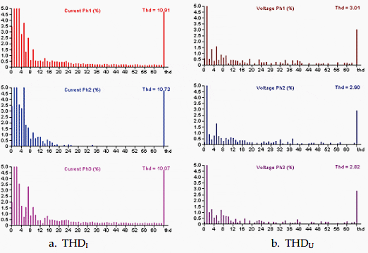
During melting period the arc furnaces also create harmonics. Arc furnaces are designed to operate at low power factor say 0.7 and 0.8. When the electrode is usually driven into the scrap metal, it produces a dead short circuit on one phase.

During arc furnace short-circuit, arc furnace demands larger reactive power from the electricity supply, in turn a larger voltage dip is produced on the system.
The flicker phenomenon does not very much affect the electric equipment, but a physiological uneasiness in vision occurs due to electric lightning flux fluctuations, which are particularly important with incandescent lamps.
Therefore, it is of crucial importance to predict these effects when an arc furnace is to be connected to a network or when an existing furnace is to be upgraded.
Static VAr compensator
To reduce harmonic injection into the system, to improve the power factor of the arc furnace during melting, to support the power supply system for VAr compensation during arc furnace short-circuit, and to balance the three-phases, a reactive VAr compensator is needed.
The static VAr compensator should be capable of supporting the system for the dynamic reactive VAr swing requirement due to arc furnaces swing from open circuit to short circuit.

The SVC offers an efficient means to rectify these shortcomings as it will keep up a high and stable voltage on the furnace bus, thereby contributing to productivity and economy of the process. The overall power factor correction for the plant provided by the SVC will also contribute in a favourable way
to process economy.
At the same time, the SVC ensures that specified limitations regarding voltage fluctuations and harmonic distortion at the point of common coupling are fulfilled for the plant.
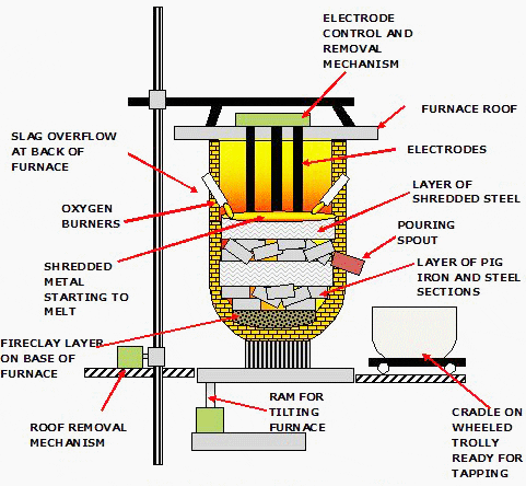
Let’s see how arc furnace works…

1. Scrap metal is delivered to a scrap bay, located next to the melt shop.
(Scrap generally comes in two main grades: shred (whitegoods, cars and other objects made of similar light-gauge steel) and hemgy melt (large slabs and beams), along with some direct reduced iron (DRI) or pig iron for chemical balance.)
2. The scrap is loaded into large buckets called baskets, with ‘clamshell’ doors for a base.
(Care is taken to layer the scrap in the basket to ensure good fizmace operation; heavy melt is placed on top of a light layer of protective shred, on top of which is placed more shred. These layers should be present in the furnace after charging)
3. The scrap basket is then taken to the melt shop, the roof is swung off the furnace, and the furnace is charged with scrap from the basket.
(Charging is one of the more dangerous operations for the EAF operators. There is a lot of energy generated by multiple tonnes of falling metal; any liquid metal in the fizrnace is ofien displaced upwards and outwards by the solid scrap, and the grease and dust on the scrap is ignited if the filmace is hot, resulting in a fireball erupting)
4. After charging, the roof is swung back over the furnace and meltdown commences.
(The electrodes are lowered onto the scrap, an arc is struck and the electrodes are then set to bore into the layer of shred at the top of the filrnace. Lower voltages are selected for this first part of the operation to protect the roof and walls from excessive heat and damage from the arcs.
Once the electrodes have reached the heavy melt at the base of the fitmace and the arcs are shielded by the scrap, the voltage can be increased and the electrodes raised slightly, lengthening the arcs and increasing power to the melt. This enables a molten pool to form more rapidly, reducing tap-t0-tap times.
Oxygen is also supersonically blown into the scrap, combusting or cutting the steel)
5. Once flat bath conditions are reached, i.e. the scrap has been completely melted down, another bucket of scrap can be charged into the furnace and melted down.
(After the second charge is completely melted, refining operations take place to check and correct the steel chemistry and superheat the melt above its freezing temperature in preparation for tapping).
6. More slag formers are introduced and more oxygen is blown into the bath, burning out impurities such as silicon, sulfur, phosphorus, aluminium, manganese and calcium and removing their oxides to the slag.
(Removal of carbon takes place afier these elements have burnt out first, as they have a greater aflinitjv for oxygen. Metals that have a poorer aflinity for oxygen than iron, such as nickel and copper, cannot be removed through oxidation and must be controlled through scrap chemistry alone, such as introducing the direct reduced iron and pig iron mentioned earlier)
7. Once the temperature and chemistry are correct, the steel is tapped out into a preheated ladle through filling the furnace.
8. During and after tapping, the furnace is ‘turned around‘.
(the slag door is cleaned of solidified slag, repairs may take place, and electrodes are inspected for damage or lengthened through the addition of new segments; the taphole is filled with sand at the completion of tapping).
EAF – Electric Arc Furnace (VIDEO)
References:
- Substation design / application guide – V AYADURAI BSC, C.Eng, FIEE
- ABB – Static Var Compensation of DC Arc Furnaces
- Power Quality and Electrical Arc Furnaces – Horia Andrei, Costin Cepisca and Sorin Grigorescu
- Harmonics and Flicker Analysis in Arc Furnace Power Systems – J. Sousa, M.T. Correia de Barros, M. Covas, A. Simoes


Dear Sir or Madam.
I am a professor at Fujairah Men’s College. I and a group of professors are writing a book (Recycling and Reusing of Engineering Materials), which will be published by Elsevier in 2022. With your generous permission, we would like to use the following Figure in one of our Book Chapters.
Could you please allow us to use this figure? We already cited your work in our chapter.
Sincerely,
Waseem Khan
Fujairah Men’s College
Wkhan1@hct.ac.ae