
Transmission line protection
The excessive currents accompanying a fault, are the basis of overcurrent protection schemes. For transmission line protection in interconnected systems, it is necessary to provide the desired selectivity such that relay operation results in the least service interruption while isolating the fault.
 The basic calculation of transmission line protection (photo credit: acrastyle.co.uk)
This is referred to as relay coordination.
Many methods exist to achieve the desired selectivity. Time/current gradings are involved in three basic methods discussed below for radial or loop circuits where there are several line sections in series.
Three Methods of Relay Grading
1. Time Grading
Time grading ensures that the breaker nearest to the fault opens first, by choosing an appropriate time setting for each of the relays. The time settings increase as the relay gets closer to the source. A simple radial system shown in Figure 1 demonstrates this principle.
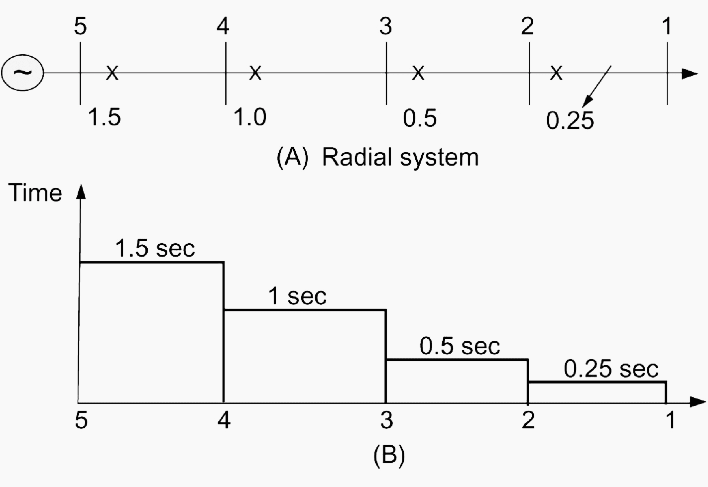
A protection unit comprising a definite time-delay overcurrent relay is placed at each of the points 2, 3, 4, and 5. The time-delay of the relay provides the means for selectivity. The relay at circuit breaker 2 is set at the shortest possible time necessary for the breaker to operate (typically 0.25 second).
The relay setting at 3 is chosen here as 0.5 second, that of the relay at 4 at 1 second, and so on. In the event of a fault at F, the relay at 2 will operate and the fault will be isolated before the relays at 3, 4, and 5 have sufficient time to operate.
Go back to Methods of Relay Grading Methods ↑
2. Current Grading
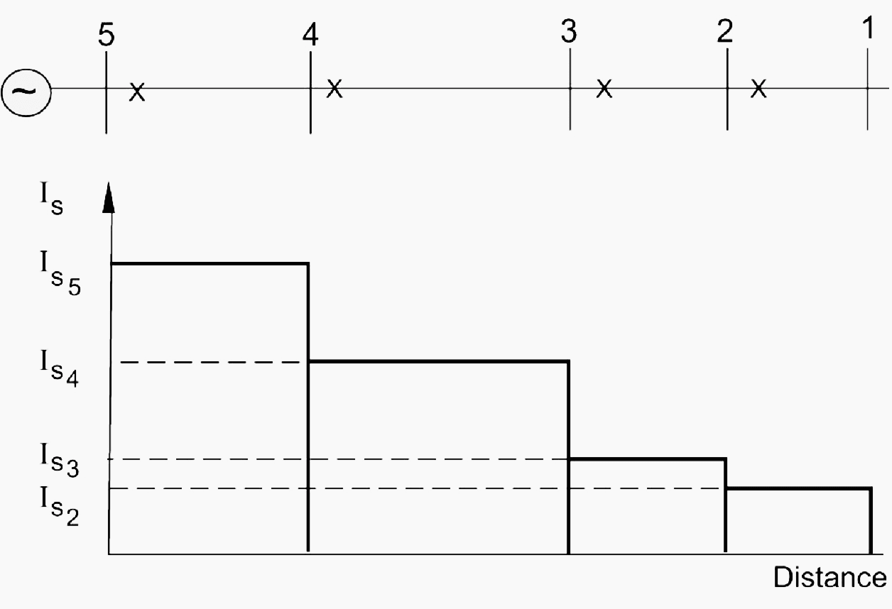
Fault currents are higher the closer the fault is to the source and this is utilized in the current-grading method. Relays are set to operate at a suitably graded current setting that decreases as the distance from the source is increased.
Figure 2 shows an example of a radial system with current grading. The advantages and disadvantages of current grading are best illustrated by way of examples.
3. Inverse-Time Overcurrent Relaying
The inverse-time overcurrent relay method evolved because of the limitations imposed by the use of either current or time alone. With this method, the time of operation is inversely proportional to the fault current level, and the actual characteristics are a function of both time and current settings.
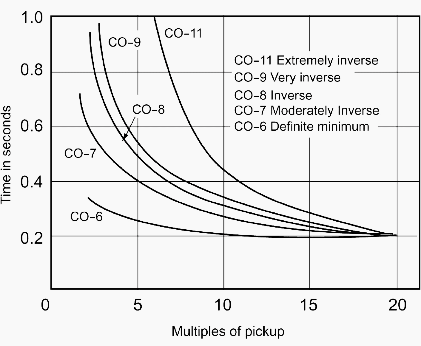
Figure 3 shows some typical inverse-time relay characteristics.
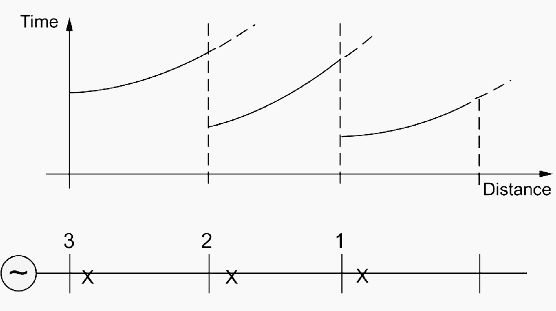
Relay type CO-7 is in common use. Figure 4 shows a radial system with time-graded inverse relays applied at breakers 1, 2, and 3. For faults close to the relaying points, the inverse-time overcurrent method can achieve appreciable reductions in fault-clearing times.
The operating time of the time-overcurrent relay varies with the current magnitude. There are two settings for this type of relay:
- Pickup current is determined by adjusted current coil taps or current tap settings (C.T.S.). The pickup current is the current that causes the relay to operate and close the contacts.
- Time dial refers to the reset position of the moving contact, and it varies the time of operation at a given tap setting and current magnitude.
The time characteristics are plotted in terms of time versus multiples of current tap (pickup) settings, for a given time dial position.
There are five different curve shapes referred to by the manufacturer:
- CO-11 Extreme inverse
- CO-9 Very inverse
- CO-8 Inverse
- CO-7 Moderately inverse
- CO-6 Definite minimum
These shapes are given in Figure 3 above.
Example with 11 kV radial system
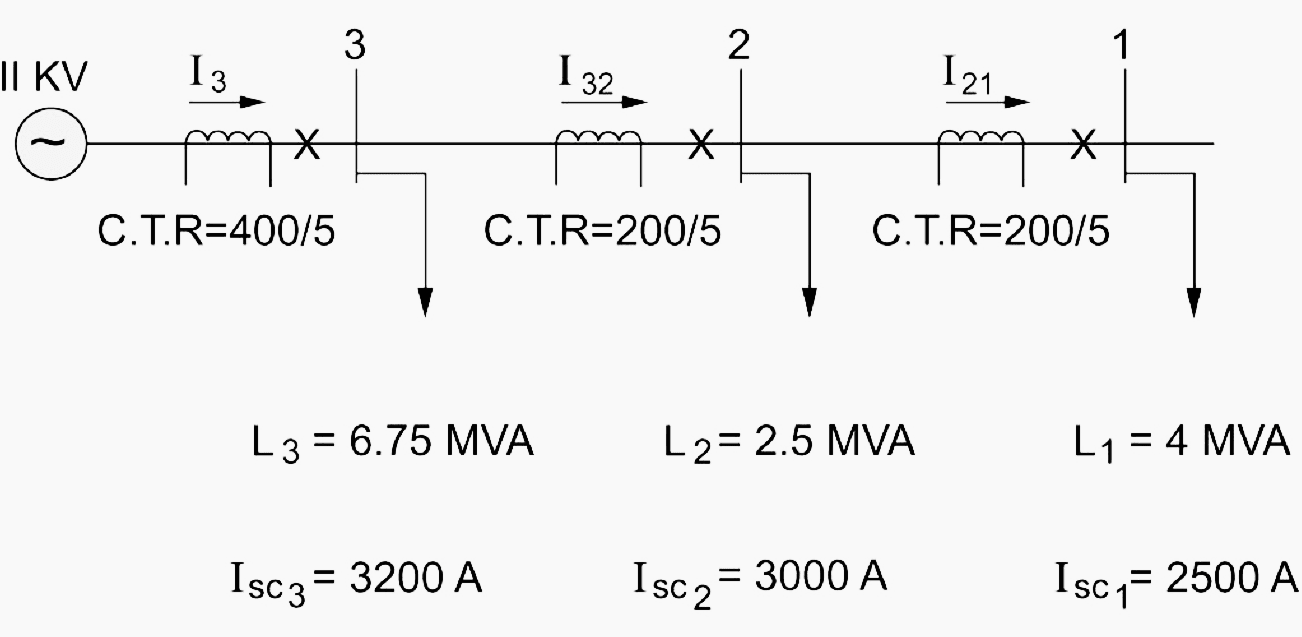
Consider the 11 kV radial system shown in Figure 5. Assume that all loads have the same power factor. Determine relay settings to protect the system assuming relay type CO-7 (with characteristics shown in Figure 6) is used:

Solution
The load currents are calculated as follows:

The normal currents through the sections are calculated as

With the current transformer ratios given, the normal relay currents are:

For position 1, the normal current in the relay is 5.25 A. We thus choose:
(C.T.S.)1 = 6 A
For position 2, the normal relay current is 8.53 A, and we choose:
(C.T.S.)2 = 10 A
Similarly for position 3,
(C.T.S.)3 = 10 A
The next task is to select the intentional delay indicated by the time dial setting (T.D.S.). We utilize the short circuit currents calculated to coordinate the relays. The current in the relay at 1 on a short circuit at 1 is:
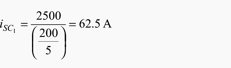
Expressed as a multiple of the pickup or C.T.S. value, we have:
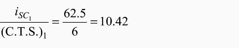
We choose the lowest T.D.S. for this relay for fastest action. Thus:

By reference to the relay characteristic, we get the operating time for relay 1 for a fault at 1 as:

To set the relay at 2 responding to a fault at 1, we allow 0.1 second for breaker operation and an error margin of 0.3 second in addition to T11 . Thus,
The short circuit for a fault at 1 as a multiple of the C.T.S. at 2 is:
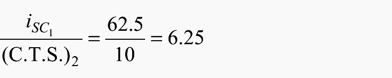
From the characteristics for 0.55-second operating time and 6.25 ratio, we get:
![]()
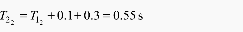
The final steps involve setting the relay at 3. For a fault at bus 2, the short circuit current is 3000 A, for which relay 2 responds in a time T22 obtained as follows:
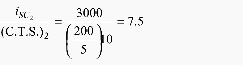
For the (T.D.S.)2 = 2, we get from the relay’s characteristic,
![]()
Thus allowing the same margin for relay 3 to respond to a fault at 2, as for relay 2 responding to a fault at 1, we have:
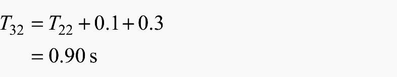
The current in the relay expressed as a multiple of pickup is:

Thus for T3= 0.90, and the above ratio, we get from the relay’s characteristic,
![]()
We note here that our calculations did not account for load starting currents that can be as high as five to seven times rated values. In practice, this should be accounted for.
Reference // Electrical Energy Systems by Mohamed E. El-Hawary (Purchase hardcopy from Amazon)
Related electrical guides & articles


Edvard Csanyi
Hi, I'm an electrical engineer, programmer and founder of EEP - Electrical Engineering Portal. I worked twelve years at Schneider Electric in the position of technical support for low- and medium-voltage projects and the design of busbar trunking systems.I'm highly specialized in the design of LV/MV switchgear and low-voltage, high-power busbar trunking (<6300A) in substations, commercial buildings and industry facilities. I'm also a professional in AutoCAD programming.
Profile: Edvard Csanyi

Dear sir/ Mam,
Thank you very much for posting such an technical material about Relay coordination. I would like to know about the TDS in detail manner. Is it possible to assume same TDS for all the Relay breakers from Upstream to down of the power flow. In the above case three different TDS values are set for the three different load cases.
why you didnt use 3200amp in short circuit current 3 in line 3 for determining T.D.S 3? please I want to be clarified thank you so much
THANK YOU FOR POSTING SUCH EDUCATIONAL DOCUMENT ESSENTIAL TO PROFESSIONAL DEVELOPMENT.
Good article, basic but well explained. I suggest to change the article´s name to “Basic calculation for line protection”, without transmission, because it is more general. In fact, time grading protection is not longer used as primary protection for transmission networks. The rules explained in this article is adecuated for radial lines.
Hello Mate,
As an Electrical Engineer in the building services industry I have really enjoyed your articles and regular information pop ups for a few years now.
One thing I have found myself doing, is copying and pasting the articles into word documents. Is there any way you could set up a downloadable PDF of the articles ? Just a suggestion I feel would enhance the excellent job you’re already doing.
Best regards,
Marc
Dear,
Congratulations for your aproach to the subject.
I would like to call your attention concerning the 11 kV system.
At this level very frequent arcing faults occur and in this case, only using overcurrent protection may not be enough as the faulty current may be significantly reduced and the source protection will not detect the fault.
The use of voltage dependant protections must be then considered so that when arcing occurs and the current be strongly reduced, the faulty condition may be detected by changing the curve level.
Particular attention must be coped for broken conductors in medium voltage level as even with voltage dependant protections there will be lot of difficulties on detecting this situation. Please refer to specific literature concerning this very delicate matter.
Kind regards.