MATLAB Simulations using Simulink for Power Electronics, Electric Motors, Generators and Solar
Learn how to use MATLAB/Simulink for power electronics circuits, electric circuits, electrical machines, solar and synchronous generators. 47 lessons in 13h 52m total course length.
Course Description
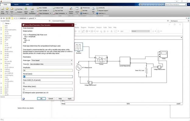
Learn the leading software MATLAB in numerical computing through step-by-step exercises. In this course, we will learn to simulate AC-DC, DC-AC, AC-AC, and DC-DC converter circuits, electric circuits, electrical machines, solar and synchronous generators in the MATLAB using Simulink tool circuits.
In this course, you will learn the simulation using MATLAB of:
- Single-phase half-wave controlled rectifier
- Model the DC machine in no-load case
- Single-phase bridge controlled rectifier
- Model the DC machine in presence of load torque
- Single-phase AC chopper with R and RL load
- Simulating the DC machine using power library
- A DC-DC converter as buck regulator
- Three-phase Inverter
- Boost regulator
- Single-phase half-wave controlled rectifier
- Buck-Boost regulator
- Induction motor
- Single-phase half-bridge inverter
- PV cell in solar energy
- Single-phase and three-phase bridge inverter
- PID controller
- Single-phase half-wave controlled rectifier
- Analyzing data from the PSCAD program
Course Summary
- Applications on Matrices in MATLAB
- Power Electronics Simulations
- Solar Energy Simulation
- DC Motor Simulation
- Induction Motor Simulation
- Synchronous Generator Simulation
- Power System Simulations
- PID Controller in MATLAB
Who Is This Course For
- Engineering students
- Practicing engineers
- Anybody with an interest in learning about power electronics and MATLAB/Simulink
Requirements
MATLAB/Simulink software, free trial available online
Downloadable course materials
After purchasing the course, students can download the following documents:
- Matlab Simulations (PDF)
- Fault Location Matlab + PSCAD (ZIP)
Course Content
About Instructor

Not Enrolled
Course Includes
- 8 Lessons
- 47 Topics
- Course Certificate
- Lifetime Access
Login
Accessing this course requires a login. Please enter your credentials below!