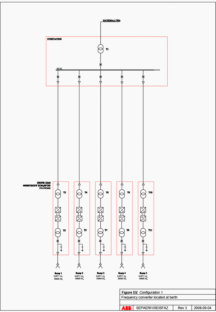
Frequency converter located at berth
This configuration is illustrated in Figure 1. This configuration is similar to the configuration recommended by the European Union. It is a decentralised system where a separate frequency is placed on each berth.

These are radially feed from a common substation. The transformer at berth serves an additional function in this configuration. It serves together with the frequency converter as a curve shaper, to form the sinusoidal curve shape.
To adapt the feeding voltage to the frequency converter additional transformer is required.
The dimensioning of the frequency converter has to be done by means of the highest power demand at the present berth, and has to have the same rated power output as transformers at berth, this to avoid being a bottleneck in the total system.

This configuration has a free-standing system at each berth which can be seen as an advantage if a fault occurs at the facility. If a fault takes place in one of the frequency converters then this berth can be disconnected without any influence on the other berths.
Even regular service work is facilitated when having a separate system according to this configuration.
The space needed for the frequency converter, two transformers and switchgears with earth switch equipment and a disconnector is approximately 190 m2.
An additional disadvantage with this configuration is that the frequency converter is used for both frequencies. When a vessel with a 50 Hz electric system is connected, the frequency converter is feeding the vessel with 50 Hz, which can be considered as excessive, since the network grid is alerady feeding the system with 50 Hz.
This is not a big problem, considering that today’s frequency converters have a high efficiency, 98-99 % but it is although noticeable at high power ranges and should be considered as a disadvantage.
| Title: | Shore-side power supply – A feasibility study and a technical solution for an on-shore electrical infrastructure for supplying vessels with electric power in port (Master of Science Thesis) – Patrik Ericsson and Ismir Fazlagic at Chalmers University of Technology, Goteborg, Sweden |
| Format: | |
| Size: | 8.20 MB |
| Pages: | 180 |
| Download: | Right here | Video Courses | Membership | Download Updates |


Please send me all information regarding electrical protection, MCC, fault finding, panel wiring, electrical protections, plc, soft start, sevor motors, Hmi, skermatic diagrams etc