
Estimated Study Time: 22 minutes
Make, withstand & break currents
A circuit breaker is both a circuit-breaking device that can make, withstand and break currents whose intensity is at most equal to its rated current (In), and a protection device that can automatically break overcurrents which generally occur following faults in installations.
 10 characteristics of LV circuit breaker you MUST know
The choice of a circuit breaker and its characteristics depends on the size of the installation as well as on the various parameters of the network.
Let’s start with circuit breaker release types, then most essential characteristics important for CB operation, then few examples of tripping curves and at the end of article – the limitation curves.
- Technologies Used For Detecting Overcurrents
- Characteristics of Circuit Breakers
- Rated Operating Voltage (in V)
- Insulation Voltage (in V)
- Impulse Voltage (in kV)
- Utilization Category
- Rated Current (in A)
- Ultimate Breaking Capacity (in kA)
- Nominal Breaking Capacity (in A)
- Standard Breaking Capacity
- Short-Time Withstand Current (in kA)
- Rated Short-Circuit Making Capacity (kA peak)
- Examples of tripping curves
- Limitation
1. Technologies Used For Detecting Overcurrents
Overcurrents are detected by three different devices: thermal for overloads, magnetic for short circuits and electronic for both. Thermal and magnetic releases, which are generally combined (thermal-magnetic circuit breakers), use an economical, tried and tested technology, but provide less flexibility of adjustment than electronic releases. On the other hand, circuit breaker with electronic release is more expensive…
Ok, let’s get into details of each of mentioned technology.
1.1 Thermal Release
This consists of a bi-metal strip which, if heated beyond the normal operating values, becomes deformed, releasing the lock holding the contacts.
Most of circuit breakers enable the trip current Ir to be set between certain limits (0.4 to 1 In depending on the CB type).

1.2 Magnetic Release
This consists of a magnetic loop whose effect releases the lock holding the contacts, thus triggering breaking if there is a high overcurrent. The response time is very short (around one tenth of a second).
Moreover this setting, when combined with a time delay, can be used to find the best discrimination conditions between the devices.

1.3 Electronic Release
A coil, placed on each conductor, continuously measures the current in each of them. This information is processed by an electronic module which controls the tripping of the circuit breaker when the values of the settings are exceeded.

The curve of the release shows three operating zones.
“Instantaneous” Operating Zone
This provides protection against high intensity short circuits. It is either set by construction at a fixed value (5 to 20 kA), or adjustable according to the device.
“Short Time Delay” Operating Zone
This provides protection against lower intensity short circuits, which generally occur at the end of the line.
“Long Time Delay” Operating Zone
This is similar to the characteristic of a thermal release. It protects conductors against overloads.
The electronic releases improve discrimination performance and some circuit breakers of the same manufacturer can also communicate with each other.
So, how it works?
Protection against overloads (long time delay trip function, ANSI code 51, AC time overcurrent relay), is identified by Function L. If the fault current exceeds the set threshold I1, this protection trips according to an inverse time characteristic, where the link time-current is represented by the relation:
I2t = K (where constant let-through energy).
With this curve, the tripping time decreases as the current increases.
The inverse time characteristic curve of function L is graphically represented, in bilogarithmic scale as shown in Figure 4 below.

The electronic trip unit makes many possible trip settings available for Function L, more precisely, a bundle of parallel lines. Each line is identifed by a time t1 (the long time delay) which represents the trip time of the protection, in seconds, in correspondence with a multiple of I1.
For example, this multiple depends on the trip unit and is equal to 3 × I1 for ABB’s breaker type ‘Emax’ CBs and 6 × I1 for type ‘Tmax’ CBs.
2. Characteristics of Circuit Breakers
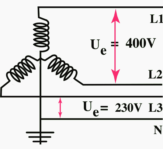
2.1 Rated Operating Voltage Ue (in V)
This is the voltage(s) at which the circuit breaker can be used. The value indicated is usually the maximum value. At lower voltages, certain characteristics may differ, or even be improved, such as the breaking capacity.
Example Single Pole Ue = 230/400 V and for Three Pole Ue = 400 V.
2.2 Insulation Voltage Ui (in V)
This value acts as a reference for the insulation performance of the device. The insulation test voltages (impulse, industrial frequency, etc.) are determined based on this value.
Example Ui = 500 V, test voltage = 2000 V
Unless otherwise stated the rated insulation voltage is the value of the maximum rated operational voltage of the circuit breaker. In no case shall the maximum rated operational voltage exceed the rated insulation voltage.
2.3 Impulse Voltage Uimp (in kV)
This value characterises the ability of the device to withstand transient overvoltages such as lightning (standard impulse 1.2/50 μs). This is actually the voltage on which clearance distances are based.
This is a voltage impulse with a 1.2/50 µs wave shape, see figure below.
Example Uimp = 4kV for 230/400V rated MCBs

2.4 Utilization Category
IEC 60947-2 designates circuit breakers as belonging to one of two categories:
- Category A for circuit breakers which do not have a time delay before tripping on a short circuit.
- Category B for circuit breakers which have a time delay. This can be adjusted in order to perform time discrimination for a short-circuit value less than Icw.
2.5 Rated Current In (in A)
This is the maximum current value the circuit breaker can withstand on a permanent basis. This value is always given for an ambient temperature around the device of 40°C in accordance with standard IEC 60947-2, and 30°C in accordance with standard IEC 60898-1.
If this temperature is higher, it may be necessary to reduce the operating current.
Example In = 32A rating, type C marked ‘C32’
2.6 Ultimate Breaking Capacity Icu (in kA)
This is the maximum short-circuit current value that a circuit breaker can break at a given voltage and phase angle (cos ϕ). The tests are executed according to the sequence O-t-CO, where:
- O represents an automatic break operation,
- t a time interval and
- CO a make operation followed by an automatic break operation.
Following the test, the circuit breaker must continue to provide a minimum level of safety (isolation, dielectric strength).
2.7 Nominal Breaking Capacity Icn (in A)
In standard IEC 60898-1, the breaking capacity of the device is tested in a similar way but is called Icn. After the test, the circuit breaker must retain its dielectric properties and be able to trip in accordance with the specifications in the standard.
NOTE! This standard applies to circuit-breakers able to make and break both alternating current and direct current.
2.8 Standard Breaking Capacity Ics
This is the value expressed as a percentage of ultimate breaking capacity Icu. It will be one of the following values: 25% (category A only), 50%, 75% or 100%. The circuit breaker must be capable of operating normally after breaking the Ics current several times using the sequence O-CO-CO.
Standard IEC 60898 gives the minimum values to be reached according to the Icn of the device.
However, it may have to break lower currents. If they are lower than the Ics of the device, this means that the installation can be restarted immediately after the break.
It should be noted that to date very few specifications or installation standards have made any reference to the Ics.
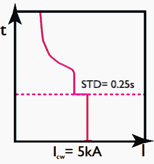
2.9 Short-Time Withstand Current Icw (in kA)
This is the value of the short-circuit current that a category B circuit breaker is capable of withstanding for a defined period without altering its characteristics. This value is intended to enable discrimination between devices.
By convention the value Icw is given for a time t = 1 s. For a different duration t, this must be indicated, for example Icw0.2. It is then necessary to check that the thermal stress I2t, generated until the downstream device breaks, is actually less than Icw2t.
2.10 Rated Short-Circuit Making Capacity Icm (kA peak)
This is the maximum current intensity a device can make at its rated voltage according to the conditions of the standard.
Devices without a protection function, such as switches, must be able to withstand short-circuit currents with a value and duration resulting from the action of the associated protection device.
3. Examples of tripping curves
3.1 250A circuit breaker with thermal-magnetic release

Where:
- I = Actual current
- Ir = Thermal protection against overloads (Ir setting = × In)
- Im = Magnetic protection against short circuits: (Im setting = × Ir)
Since the abscissa of the curves expresses the I/Ir ratio, modifying the Ir setting does not change the graphic representation of thermal tripping.
However, the magnetic setting Im can be read directly (3.5 to 10 in this example).
3.2 1600A circuit breaker with electronic release

Where:
- I = Actual current
- Ir = Long delay protection against overloads (adjustable: Ir = × In, 0.4 to 1 × In)
- Tr = Long delay protection operation time (adjustable: 5 to 30 s) up to 6 x Ir
- Im = Short delay protection against short circuits (adjustable: Im = × Ir, 1.5 to 10 Ir)
- Tm = Short delay protection operation time (adjustable: 0 to 0.3 s)
- I2t = Constant (adjustable via Tm)
- If = Fixed threshold instantaneous protection (fixed: 5 to 20 kA depending on the model)
3.3 Example of setting a circuit breaker and reading the curves
Here: IB = 500 A and Ik3max = 25 kA at the installation point. Protection can then be provided by an circuit breaker with electronic unit, rating 630 A, long delay setting (overload) Ir = 0.8 × In, i.e. 504 A.

Scenario 1: High min. Isc
Isc min. (at end of line) = 20 kA
⇒ short delay setting (short circuit) Im = 10 × Ir, i.e. 5040 A
Reading the curves:
- If I < 504 A ⇒ no tripping
- If 504 A < I < 5 kA ⇒ tripping between 1 and 200 s (long delay protection)
- If I > 5 kA ⇒ tripping in 0.01 s (fixed threshold instantaneous protection)
Scenario 2: Low min. Isc
Isc min. (at end of line) = 4 kA
⇒ short delay setting (short circuit) Im = 5 × Ir, i.e. 2520 A
Reading the curves:
- If I < 504 A ⇒ no tripping
- If 504 A < I < 2520 A ⇒ tripping between 6 and 200 s (long delay protection)
- If 2520 A < I < 5 kA ⇒ tripping < 0.1 s (short delay protection)
- If I > 5 kA ⇒ tripping in 0.01 s (fixed threshold instantaneous protection)
Scenario 3: Cable thermal stress limited
Isc min. (at end of line) = 20 kA
Conductor 10 mm2, permissible thermal stress: 1.32 × 10⁶ A2s, i.e. 3633 A for 0.1 s
⇒ short delay setting (short circuit) Im = 7 × Ir, i.e. 3528 A (< Ith of the cable)
Reading the curves:
- If I < 504 A ⇒ no tripping
- If 504 A < I < 3528 A ⇒ tripping between 3 and 200 s (long delay protection)
- If 3528 A < I < 5 kA ⇒ tripping < 0.1 s (short delay protection)
- If I > 5 kA ⇒ tripping in 0.01 s (fixed threshold instantaneous protection)
3.4 MCB Limits
For secondary circuit breakers (MCB – miniature circuit breakers), standard IEC 60898-1 specifies the limits within which tripping on short circuits should take place:
- Curve B: 3 to 5 In
- Curve C: 5 to 10 In
- Curve D: 10 to 20 In
Other types of curve can also be used:
- Curve Z: 2.4 to 3.6 In
- Curve MA: 12 to 14 In
Main tripping curves for miniature circuit breakers:

As a general rule, curve C circuit breakers are used for standard distribution applications. It may be necessary to use curve B circuit breakers for low short-circuit currents (long cables, secondary circuit breaker in IT or TN system, alternator, etc.).
MA (magnetic only) circuit breakers are used for circuits where thermal protection is prohibited or provided by other methods: safety circuits in public buildings, motor circuits, transformers, etc.
4. Limitation
If there is a short circuit, without any protection, the current that would flow through the installation is the prospective short-circuit current.
When a short-circuit current crosses a circuit breaker, the circuit breaker has the capacity, to a greater or lesser extent, to allow only part of this current to flow. The short circuit is then limited in amplitude and duration.
The purpose of limitation is to reduce:
- Thermal stress
- Electrodynamic forces
- Effects of electromagnetic induction
It also makes discrimination and combination easier. The limitation capacity of devices is represented in the form of limitation curves
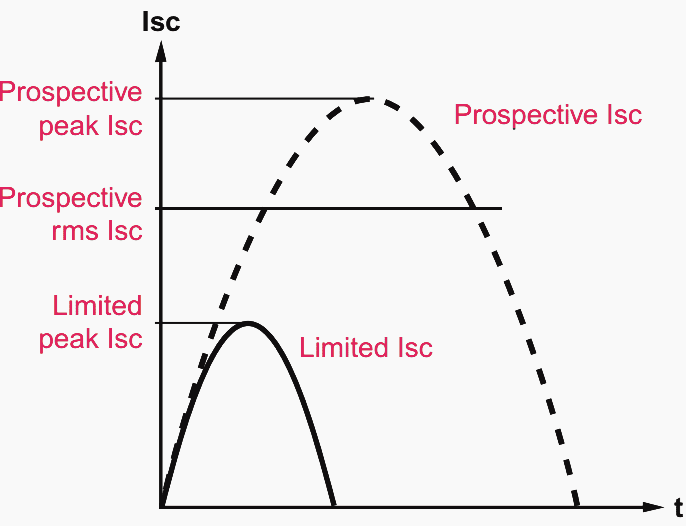
4.1 Current Limitation Curves
These give the maximum peak current values (in A peak), limited by the devices according to the value of the prospective short-circuit current. The limited current values are used to determine the size of the busbars and to check the withstand of conductors and devices.

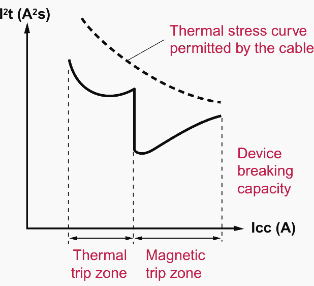
4.2 Thermal Stress Limitation Curves
These give the image of the energy (A2s) that the device allows to flow according to the prospective short-circuit current. They can be used to check the thermal stress withstand of cables protected by the device.
References:
- Breaking and protection devices by Legrand
- Low voltage circuit breakers Working with trip characteristic curves by ABB
- Guide to Low Voltage Circuit-Breakers Standards – In accordance with BS EN 60898-1, BS EN 60898-2 and BS EN 60947-2 by BEAMA
Related electrical guides & articles


Edvard Csanyi
Hi, I'm an electrical engineer, programmer and founder of EEP - Electrical Engineering Portal. I worked twelve years at Schneider Electric in the position of technical support for low- and medium-voltage projects and the design of busbar trunking systems.I'm highly specialized in the design of LV/MV switchgear and low-voltage, high-power busbar trunking (<6300A) in substations, commercial buildings and industry facilities. I'm also a professional in AutoCAD programming.
Profile: Edvard Csanyi

Great Job! Refreshing of Tech. Theory, like daily breakfast.
Wow, this is so much easier to understand that any other manual or publications out there on how LV circuit breakers! Thank you for this and for what you do!
A circuit breaker curve is Time vs Current. What exactly is the Time measurement? Is it the duration of the Inrush pulse and if so where is it measured? As you go up in amplitude on the pulse the duration gets narrower.
Very Important
Good job sir..
Where we can find the , multiplying factor and cpt
A must read for Electrical Practitioner! Thank Edvard
You’re welcome Arnel! Glad you like it.
Fantastic!
It’s an important information.
very good. Thank u very much.
Akram
Very insightful presentation on circuit breakers.
Great Definition & Explanation of circuit breakers & thier operating characteristics.
Please explain why Icw values are less in magnitude like 5kA? Explain it’s calculation with example.
EXCELLENT EXPLANATION. THANKS FOR SUCH VALUED TECHNICAL LITERATURE.
well explained & illustrated technical information on lv Switch gear keep it up.