Gas engine power plant equipment
This document covers the types of machinery used in the 33MW gas engine power plant, the operating and controlling of these machines, transformer, troubleshooting, switchyards, and its protection systems, what equipment is placed in which zone, how the equipment has been synthesized, etc. The scope will be limited to only this type of power generation and transmission system.

Control and Safety Zone
The generating set can be operated in automatic or manual mode. The control mode selection is made with the “generating set control” switch on the manual control unit. In automatic mode, the control system selects the engine and generator control methods according to the “parallel with grid” signal.
In manual mode, the engine and generator control modes are selected with switches on manual control unit. Some control modes are enabled only when the generating set is in parallel with the grid.
Parallel operation
If the generating set is in parallel with the grid, the grid will determine the frequency and voltage. Any fluctuation in grid voltage or frequency is followed by the generating set. An increase or decrease in the output of the generating set does not affect the network frequency or voltage, provided that the power plant is relatively small compared to the total network capacity.
Parallel operation requires that the generating set is synchronized with the grid.
Island operation
In island operation mode, the power plant feeds an isolated network. The control system of the power plant controls the frequency and voltage in the network.

Control functions
The main functions of the control system are:
- Start and stop of the generating set
- Synchronization
- Engine speed and load control
- Generator output control
- Control of auxiliary systems
- Monitor and alarm handling
- Safety functions, such as start blocking, shutdown and load reduction.
The generating set can be controlled in automatic or manual mode. In automatic mode, which is the normal operating mode, the control system takes care of start and stop, loading and unloading, and generator output control.
In manual mode, the loading and unloading as well as the generator output control must be done manually by the operator. The safety functions, such as checking of the start conditions, work in the same way as in automatic mode.
Engine Starting Condition
Engine start is enabled when the following starting conditions are to be met.
- Lube oil pressure >0.6 Bar
- HT- water temperature >450C
- Engine speed=0
- Valve power supply>18vdc
- Safety wire ok
- Turning gear disengaged
- External start block
- WECS ready for start
- Exhaust gas ventilation
- Engine is not running
- Stop command inactive
- Shutdown alarm inactive
- Tripping alarm inactive
- Earthing disconnector open
- Breaker truck in service
- PLC- WECS communication
Automation System
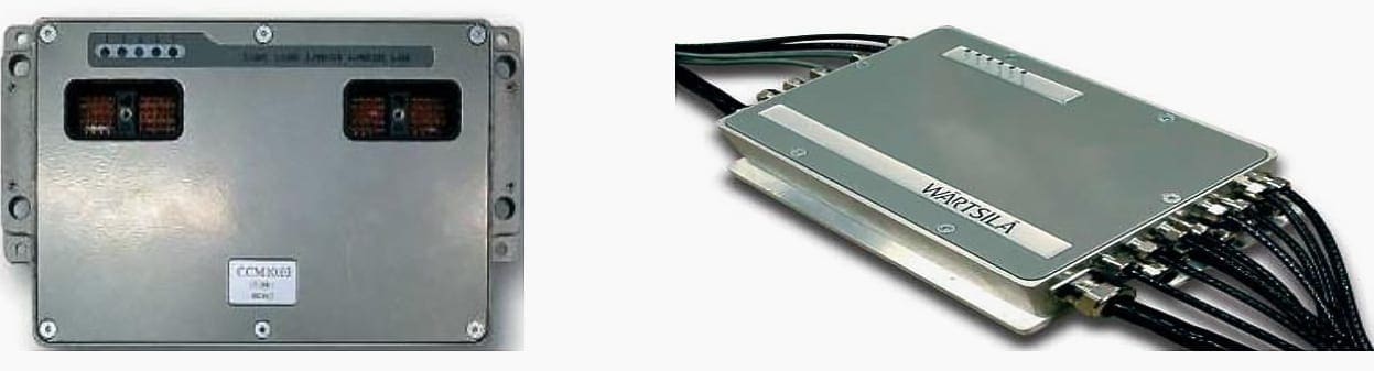
The Engine Control System is an engine-mounted distributed system. The various electronic modules are dedicated to different functions and communicate with each other via a CAN data bus. All parameters handled by the Engine Control System are transferred to the operator interface and the plant control system.
Its features are:
- Easy maintenance and high reliability due to rugged engine-dedicated connectors, CIB´s (cabling interface boxes) and high quality cables
- Less cabling on and around the engine
- Easy interfacing with external system via a data bus
- Digitized signals giving immunity from electromagnetic disturbance
- Built-in diagnosis for easy troubleshooting
It is the Work Station of the Power house which incorporates the following major control units:
- PLC (Programmable Logic Controller)
- WOIS (Wartsila Operator Interface System)
- WISE workstation
- CRP (Control Relay Panel)
- Energy Metering Panel
- CFA901 Panel
- CFC Panel
- Auto-Synchronizer
- Differential Relay
- Distance Relay
- U/f Relay
- AVR (Automatic Voltage Regulator)
- DC Charger Panel
- Speed droop control
PLC (Programmable Logic Controller)
The programmable logic controller (PLC) system is the core of the control system. The PLC system includes a PLC for each generating set, and a common PLC. Each PLC includes a central processing unit (CPU), which contains the control functions, and a number of I/O cards for collecting and transmitting process signals.
The PLC system controls the operation of the generating sets and some of the auxiliaries. It collects data, executes controls, generates alarms and performs measurement scalings for the WOIS terminal.
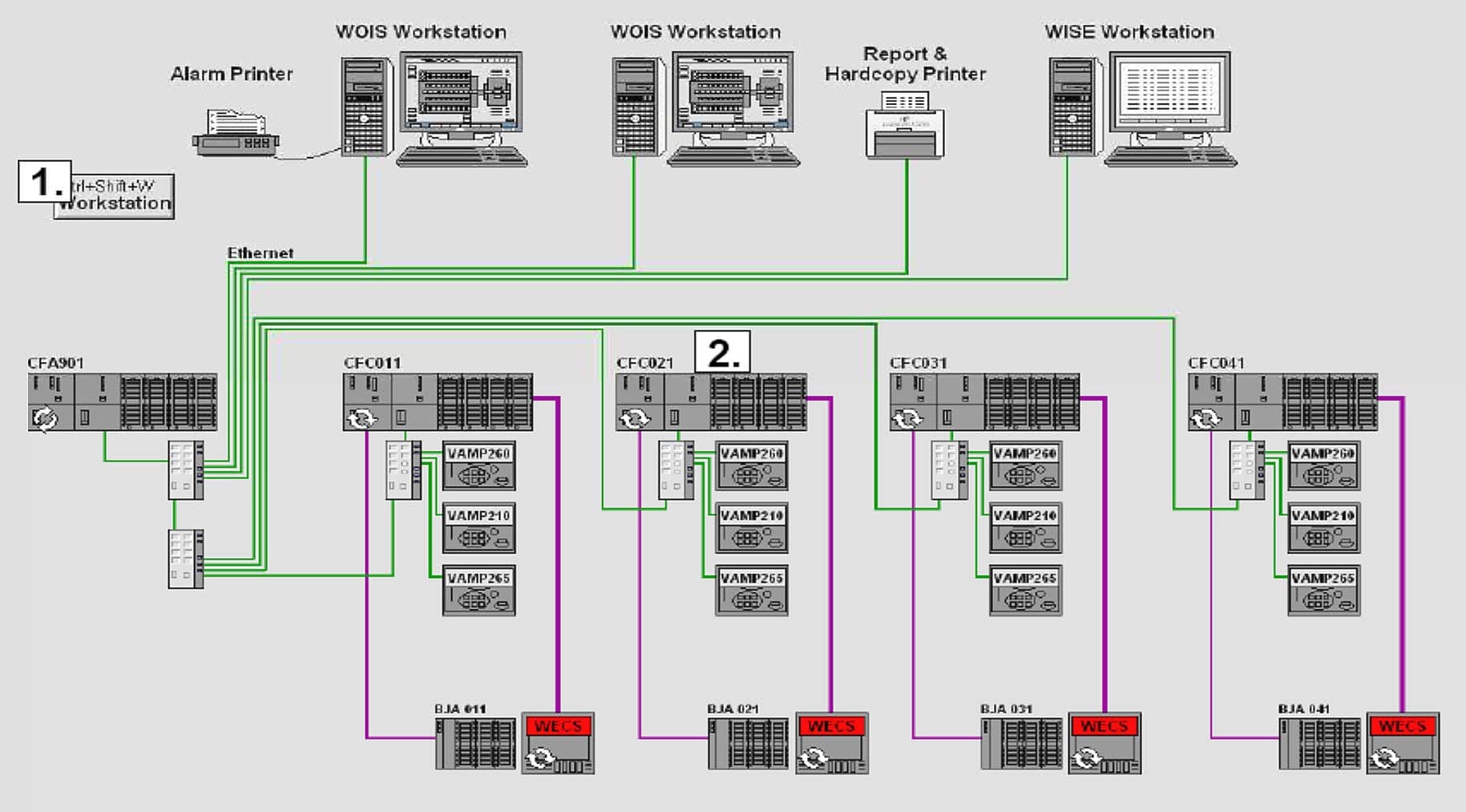
The main control functions of the generating set PLC are engine start and stop, engine speed and load control, generator output control, synchronization and control of auxiliary systems. The engine speed is controlled by the PLC together with the engine control system.
The PLC system consists of one common PLC, one engine vice PLC and one WECS per Gen-set and one operator’s station. For this system Ethernet is used for communication between the PLCs and the operation’s station. The WECS system controls and monitors the engine while the PLC controls and monitors engine auxiliaries and common systems.
The WECS and PLC system collect and scale data from the inputs and sends the data to the operator’s station through the Ethernet.
| Title: | Machinery used in power generation and substation of 33MW gas engine power plant – Saiful Islam, Department of Electrical and Electronics Engineering, IUBAT- International University of Business Agriculture and Technology |
| Format: | |
| Size: | 9.5 MB |
| Pages: | 116 |
| Download: | Right here | Video Courses | Membership | Download Updates |