Auxiliary system design
Power plant auxiliary system is usually pretty complicated and consists of dozen of motors, transformers, capacitor banks, variable frequency drives, PLCs, and other electrical devices. Therefore, protection relaying cannot be simple, and it requires special attention for each component of a power and control system as well as coordination between them.

This technical article will shed some light on how an auxiliary system should be designed in order to sustain the main production facilities in power plants. Special attention is given to the protection coordination of motors, transformers, and other devices from the point of view of the normal and emergency operation of the entire plant.
Faulted electrical equipment MUST be removed from service as fast as possible. For many electrical faults or abnormal events within the plant this may require that the generator be removed from the system, the excitation system tripped, the turbine valves closed and the boiler fires extinguished. Often this is not acceptable.
In addition, the auxiliary system must be configured to allow the unit to return to service as soon as possible.
Auxiliary system of a unit-connected generator
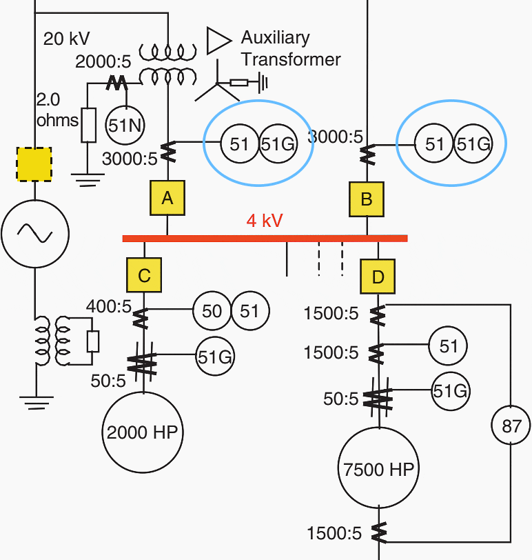
A portion of a typical auxiliary system of a unit-connected generator is shown in Figure 1 below.
The 4 kV auxiliary bus is fed directly from the 20 kV generator leads or from the startup transformer and is the source for the major motors. As unit sizes increase, the auxiliary load increases proportionately, requiring higher rated transformers and higher rated, higher voltage motors. This has resulted in higher bus voltages, such as 6.9 kV and 13 kV.
Phase fault currents also increased, requiring switchgear with higher interrupting capacity. In sizing the switchgear there are two contradictory factors that must be considered. The impedance of standard transformers increases as their ratings increase.
Since the normal and short-circuit currents are also increasing, there is a greater voltage drop between the auxiliary bus and the motor.


Normal design practice is to maintain at least 85 % voltage at the motor terminals during motor starting. If the standard transformer impedance is specified to be at a lower value to reduce the voltage drop and maintain the 85 % voltage criterion, the interrupting current will increase requiring larger rated switchgear
If the transformer impedance is raised to reduce the fault current, and hence the interrupting capacity requirement of the switchgear, the voltage drop will be too high.
The art of designing the auxiliary system must take all of these factors into account. Transformers can be specified with special impedances at a greater cost. The auxiliary system can be designed with several bus sections thus reducing the transformer rating for each section.
Current-limiting reactors can be used either as separate devices or incorporated in the switchgear.
In addition to the 4 kV (or higher) bus, a lower voltage auxiliary bus system is used to feed the dozens or hundreds of smaller motors, heating and lighting loads that are present in the plant. The nominal voltage rating of this lower voltage bus system can be 600 or 240 V.
The lower voltage buses are energized from the higher voltage bus as shown in Figure 1.
The circuit breakers used on the lower voltage buses are included in the metal-enclosed switchgear and are covered in ANSI standards C37.20-1 and C37.20-3. They may not be draw-out type necessarily, don’t have CTs and may be mounted in motor control centers.
Circuit breakers may be air type or molded case breakers with limited interrupting capacity. Protection is provided by series trip coils or thermal elements.
Which type of circuit breaker?
There are many circuit breaker designs depending upon the particular application:
- Oil circuit breakers
- Air circuit breakers
- Vacuum circuit breakers
- Sulfur hexafluoride (SF6) circuit breakers
Vacuum circuit breakers extinguish the arc in a gap of less than 13 mm (0.5 in) because there are no constituents in the vacuum that can be ionized to support the arc. Sulfur hexafluoride (SF6) circuit breakers extinguish the arc using one of two methods: the puffer design blows the arc out with a small amount of gas blasted in a restricted arc space; the rotating arc design uses the electromagnetic effect to rotate the arc through SF6 that cools and extinguishes it.
Nowadays, vacuum and SF6 circuit breakers are more commonly used. More about which one and where to apply, you can learn here. These circuit breakers are mainly drawout type, allowing the breaker to be removed for maintenance.
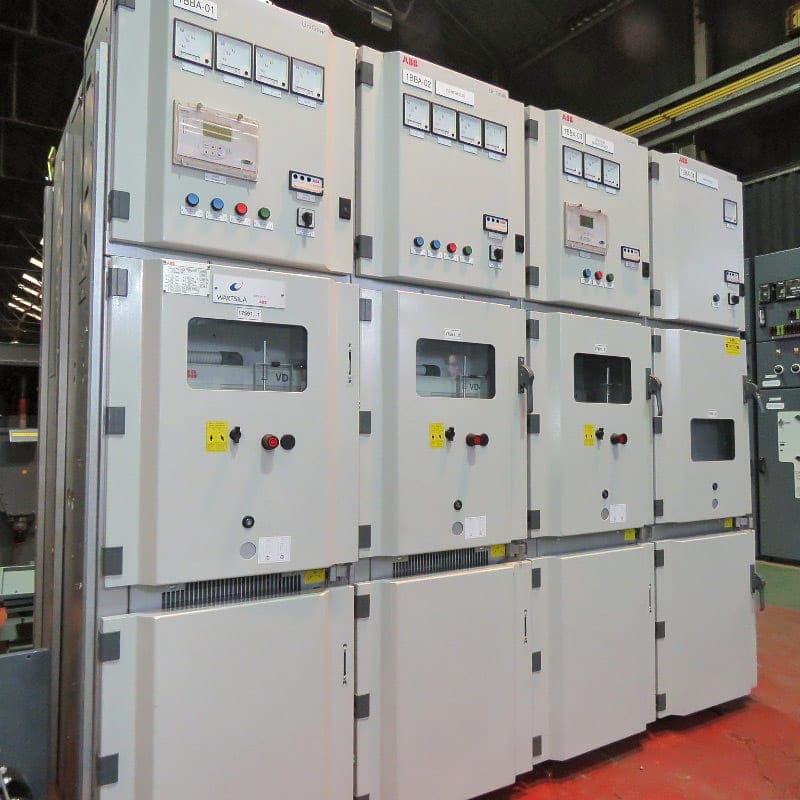

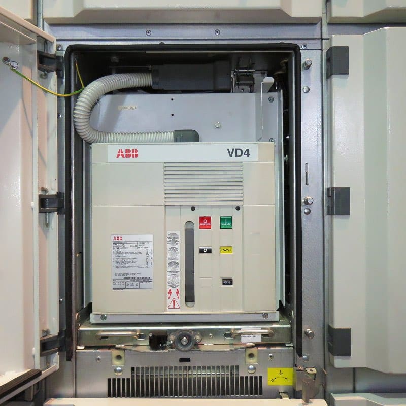

Buses rated above 2400 V use metal-clad switchgear as defined in ANSI standard C37.20-2. The switchgear compartment contains the CTs, auxiliary contacts and, usually, the relays and meters.
Phase fault protection (51)
The phase overcurrent relays (51A and 51B) on the secondary of the unit auxiliary and startup transformers provide bus protection and backup relaying for individual motor protection and switchgear.
Figure 1 indicates the general arrangement of the buses and loads and shows the protection of the 2000 hp motor and the 7500 hp motor.
If the relays are also the primary bus protective relays, the settings may be so high that there may not be enough bus fault current to provide sufficient margin to ensure pickup for the minimum bus fault.

Even if coordination is theoretically possible, the required time delay may be too long to be acceptable. Some compromises are possible. Since the largest motors will probably have differential protection, the backup function could consider coordinating with the overcurrent relays of the smaller motors with an associated reduction in pickup.
A bus differential relay could be used to provide primary protection and the overcurrent relays provide backup protection for motor relay or switchgear failures. The time delay may then be acceptable. The pickup setting must still recognize the magnitude of starting current of the largest motor.
If it cannot be set above this value, an interlock must be provided which will block the backup relay.


The overcurrent backup relay will see the total current supplied to the bus, whereas the differential relay only sees the difference between supply current and load current as discussed previously. The relay settings for overcurrent backup protections are somewhat difficult and usually employ an instantaneous and timed component.
After all, the objective is that breakers X and Y should clear the fault before the backup protection operates to trip the main supply breaker S.
Never underestimate ground fault protection
The importance of ground fault protection cannot be overemphasized. Ground is considered to be involved in 75–85 % of all faults. In addition, phase overcurrent may often reflect a temporary process overloading, while ground current is almost invariably an indication of a fault.
It is not uncommon for systems of 600 V and less to be delta-connected. Medium-voltage systems (5 kV to 15 kV) are generally operated in wye, with a neutral resistor to limit the ground current to some definite value.
The resistor has a time-related capability, e.g. 10 s, at the maximum ground current and it is a function of the ground protective system to remove all faults within this time constraint.


In Figure 6, ground faults on the 4 kV system are limited by the 2.0 Ω neutral resistors in the auxiliary and startup transformers. The magnitude of the maximum fault current is the lineto-ground voltage divided by the 2.0 Ω resistor. The nominal voltage of the bus is 4 kV but its normal operating voltage is 4160 V.
Therefore, the maximum ground current is 4160/(√3 × 2) or 1200 A.
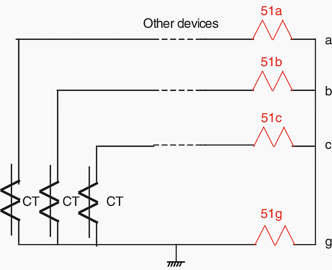
Coordination must, of course, begin at the load. If the motor ground overcurrent protection is provided by the toroidal CT shown in Figure 7 there is no coordination problem.


These can have a ratio of 50:5 resulting in a relay current of 120 A. Set an instantaneous relay at 5.0 A. If a residual ground relay is used as shown in Figure 8, the maximum ground fault through the CTs on breakers A and B is 1200/600 = 2.0 A. Set the time-delay ground overcurrent relays at 0.5 A and 15–30 cycles.
The motor relays trip the associated feeder breaker, 51A and 51B trip the 4 kV main breakers and the neutral relays 51N trip their associated primary breakers.

Bus transfer schemes (alternative source)
It is common practice to provide a bus transfer scheme to transfer the auxiliary bus to an alternative source in the event of the loss of the primary source. In power plants, the purpose of this alternative source is not to maintain normal operation but to provide a startup source, to act as a spare in the event an auxiliary transformer fails and to provide for orderly and safe shutdown.
In industrial plants, the alternative source might have a different purpose, such as to provide flexibility in production or supply some facilities from the utility and others from a local generator.
Some schemes monitor this residual voltage and allow closing to the alternative source only after this voltage has been significantly reduced.


Generator breaker (needed or not?)
Figure 10 shows a generator breaker as an alternative facility. This is common for generators that are connected to a common bus, such as in a hydro plant. With the advent of the unit system, however, this configuration has not been used as often. The unit system requires that the boiler, turbine, generator and GSU transformer be operated as a single entity and the loss of any one element requires that all of them be removed from service.
Not only is such a breaker extremely costly, it must be placed between the generator and the step-up transformer, which adds considerable length to the building. This introduces costs to every segment of the construction and installation.


Nevertheless, the generator breaker has can be extremely useful. Its most important advantage is the fact that, for a fault on the generator or auxiliary buses, without a generator breaker to remove the generator contribution from the fault, the generator will continue to feed the fault until the generator field decays. This can take as much as 7–10 s.
During this time the energy in the fault will result in extensive physical damage to all of the connected equipment and greatly increases the possibility of fire.
If the startup transformer is connected to some other system, then breaker B must be closed with synchronizing relays. If a generator breaker is provided, at startup the generator breaker is open and the auxiliary buses are fed through the GSU transformer and 4 kV breaker A.
Sources:
- Power System Relaying by Stanley H. Horowitz, Arun G. Phadke (purchase the hardcover from Amazon)
- Science and Reactor Fundamentals – Electrical | CNSC Technical Training Group
- Switchgears book by BHEL – Bharat Heavy Electricals Limited




I would respectfully add four items to keep in mind as one begins the electric supply (auxiliary electric system) design for any project/process.
1) – Know what we are – We are human!
2) – Know our place – We provide a fabulously convertible energy source that enables automation for which we are rarely knowledgeable of the automation process we are enabling!
3) – What we must do first – Develop an understanding of the project/process mechanically (or chemically, structurally, hydraulically, aerodynamically, etc.) by listening to the client.
4) – Verify our limited knowledge – Describe to the client how the project/process functions and take notes as they educate us on what we thought we understood. Leave your ego at the door.
4) – Repeat the above
Good reference. It shows important function of each component in the system.
I would like to know all of this topic..
I’m confident to always refer to your portal in future for consultative purposes
I’m extremely interested in your portal, mind refreshing for technicians, like I’m coming out of a seminar
I need understanding directional over current & directional earth fault