
Estimated Study Time: 32 minutes
11kV/415V Substation Design
The design of a low-voltage substation is a pretty complex and quite exciting job to do. If the designer would have complete freedom to make decisions regarding the substation layout, equipment, or cable routes, the job will be even more challenging! Well, this article will try to shed some light on the main design aspects of the 11kV/415V substation layout, structure, earthing and fire suppression systems.
 Design Knowhow: Low voltage substation layouts, earthing, fire protection and tests
Since this type of substation is implemented to feed and distribute power to an entire project, learning about the major design considerations and the required clearances inside the room becomes necessary.
The design of a substation inside a building may have different design layouts that need to be studied to know more about how electrical equipment, such as transformers, LV panels, RMUs etc., are installed inside the room.
Different layouts are elaborated on in this article. The equipment inside the substations MUST be protected from potential fire incidents, which means that a substation must contain different types of firefighting and fire alarm systems that are interfaced together to provide full protection in case of fire.
This article explains the major tests that need to be carried out step by step to deliver a safe, reliable and protected substation.
- Structure of an LV Substation
- How to Start With the Design?
- Fire protection Interfacing Inside an LV substation
- Earthing System inside an LV Substation
- Requirements Before Testing LV Panels
- Tests After Erection of LV Panels
1. Structure of an LV Substation
An LV substation or an LV room typically contains standing switchboards and other equipment required for the room to function, such as bus ducts and cable containments, panel boards, capacitor banks, air conditioning system, fire alarm system, firefighting system, lighting, small power etc. The latter systems are required to build a typical indoor LV substation.
However, before indulging into more details about the LV substation’s structure, it is crucial to have a brief on how the medium voltage substations, including the MV switchgear and the transformer, supply an LV substation.
Electricity is first generated in power plants or stations with a voltage of 11kV, then stepped up using step-up transformers to increase the voltage to between 100 kV to 700kV depending on the distance it will be transferred to; the longer the distance, the higher the voltage.
After that, electricity is transmitted via overhead electrical lines, which you can see when you drive between cities (see bottom for ‘Commercial load’).
Figure 1 – A 24-bus system, showing generation, transmission, subtransmission, industrial, and commercial loads
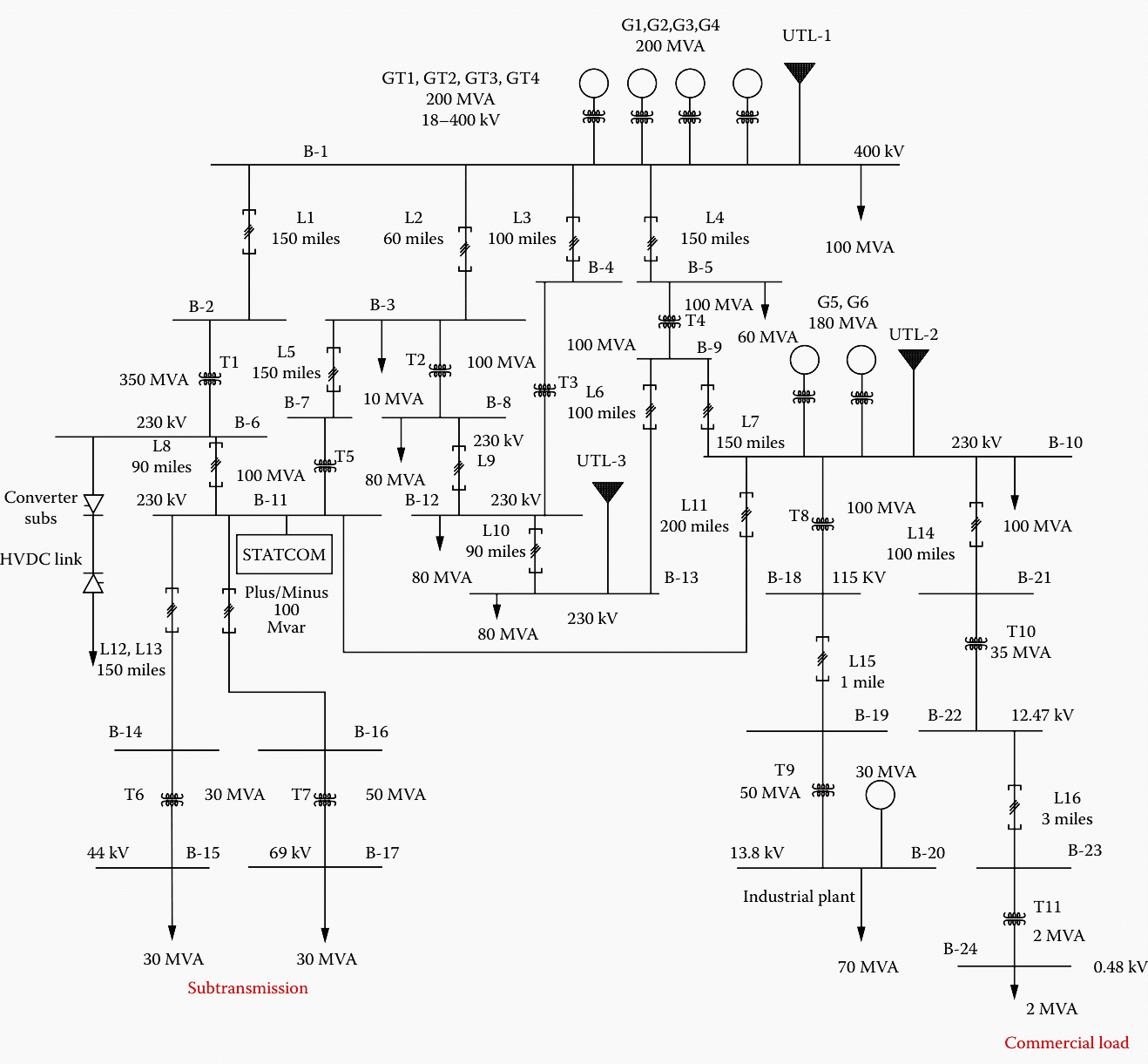
The transmission of these lines is aimed at reaching several receiving HV substations. When electrical power reaches a receiving station, the voltage decreases to 33kV and 66kV. It is then sent to transmission lines from this receiving station to electrical substations close to cities, villages, and urban areas. When electrical power reaches a substation, it is stepped down once more by a step-down transformer to voltages closer to what it was generated at, usually around 11kV.
From here, the transmission phase graduates to the distribution phase, and electrical power is used to meet demand from primary and secondary consumers. This is done by installing an MV voltage switchgear/ RMU (Ring Main Unit) that can supply several low-voltage transformers that decrease this voltage to 500V or less for distribution and utilization purposes.
By looking at the figure below, we can understand more what makes up an LV substation.
Figure 2 – Low voltage substation
Go back to the Contents Table ↑
2. How to Start With the Design?
Designing the LV part of an LV substation can only be done by taking some considerations in mind. The 11kV/0.45kV substation can either be located indoors or outdoors. The most likely type of LV substation used for supplying customers with less than 500V is located inside the building and distributes power to the entire project, and should be designed to meet the safety requirements to avoid any dangerous situations.
The LV substation MUST be designed to provide a reliable service, facilitate maintenance and allow for future expansions.
In other words, at least 20% spare capacity should be provided for every equipment inside the room, including cable trays, trunks, LV switchboards, etc. Below are some major requirements that must be complied with inside an LV substation.
- Access for personnel (normal and emergency).
- Access for equipment (installation, operation and maintenance).
- Regulatory compliance and approvals.
- Cable containment and entries.
- Earthing and grounding.
- Water sealing (if below ground).
- Air conditioning, lighting & small power.
- Fire detection, alarm and suppression.
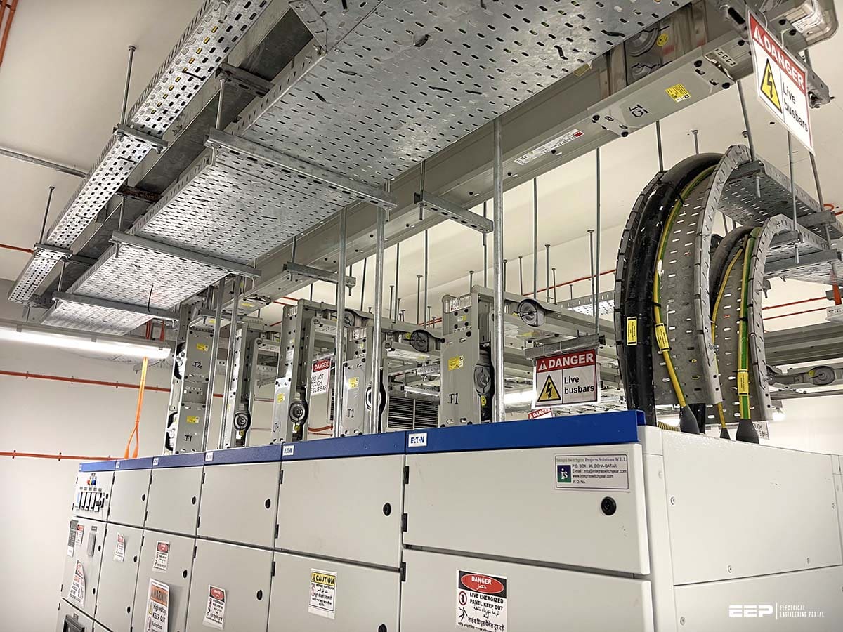
Figure 3 – Inside an LV/MV Substation

Go back to the Contents Table ↑
2.1. Equipment Clearances You MUST NOT Be Wrong About
The internal clearances of an low voltage room must always follow international standards like NEMA, BS and NFPA. Equipment such as trays, LV switchgear, capacitor banks etc., are usually located and placed following these standards. In many countries, LV substation design drawings are be approved by the main electrical authority before building construction.
This is why dimension considerations must be made during the design stage.
Electrical authorities might only supply the building with power if the requirements are met. In a typical LV substation, cable trays are installed to facilitate the outgoing and incomer cables. These trays should be designed to be located with sufficient clearances around them to permit adequate access for the installation and maintenance of cables.
Related electrical guides & articles


Mohammed Ayman
I earned my degree from Eastern Mediterranean University (Turkey, North Cyprus) in B.S Electrical & Electronic Engineering; shortly after, I began my career as an electrical site engineer in a mega-scale project in Qatar which allowed me to monitor and supervise electrical site installations. I indulged in the design field of the electrical low voltage distribution systems and have accomplished more than 10 projects with the compliance of the national codes & international standards.Profile: Mohammed Ayman
