Introduction to GIL
GIL systems are based on the successful SF6 tubular conductor technology, which has been around for several decades. GIL consist of a central aluminum conductor with a typical electrical cross section of up to 5,300 mm2.
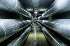
 System Design (on photo Tunnel-Laid GIL by SIEMENS)")
The conductor rests on cast resin insulators, which center it within the outer enclosure.
This enclosure is formed by a sturdy aluminum tube, which provides a solid mechanical and electrotechnical containment for the system. To meet up-to-date environmental and technical aspects, GIL are filled with an insulating gas mixture of mainly nitrogen and a smaller percentage of SF6 gas.
This concept also has logistic advantages. All elements such as tubes, angles and special modules are lightweight and small enough to be transported by comparatively light standard trucks.
 Construction")
Technical Data
The main technical data of the GIL for 420kV and 550kV transmission networks are shown in table below.
For 550-kV applications, the SF6 content or the diameter of the enclosure pipe might be increased. The rated values shown in table below are chosen to match the requirements of the high-voltage transmission grid of overhead lines.
Table – Technical Data for 420kV and 550kV GIL Transmission Networks
| Type | Value |
| Nominal voltage (kV) | 420/550 |
| Nominal current (A) | 3150/4000 |
| Lightning impulse voltage (kV) | 1425/1600 |
| Switching impulse voltage (kV) | 1050/1200 |
| Power frequency voltage (kV) | 630/750 |
| Rated short-time current (kA=3s) | 63 |
| Rated gas pressure (bar) | 7 |
| Insulating gas mixture | 80% N2, 20% SF6 |
The power transmission capacity of the GIL is 2000 MVA whether tunnel laid or directly buried. This allows the GIL to continue with the maximum power of 2000 MVA of an overhead line and bring it underground without any reduction in power transmission.
The values are in accordance with the relevant IEC standard for GILs, IEC 61640.
Standard Units
Figure 1 shows a straight unit combined with an angle unit.
The straight unit consists of a single-phase enclosure made of aluminum alloy. In the enclosure (1), the inner conductor (2) is fixed by a conical insulator (4) and lies on support insulators (5).

The thermal expansion of the conductor toward the enclosure is adjusted by the sliding contact system (3a, 3b). One straight unit has a length up to 120 m made by single pipe sections welded together by orbital-welding machines.
If a directional change exceeds what the elastic bending allows, then an angle element (shown in Fig. 1) is added by orbital welding with the straight unit. The angle element covers angles from 4° to 90°. Under normal conditions of the landscape, no angle units are needed because the elastic bending, with a bending radius of 400 m, is sufficient to follow the contour.
At distances of 1200–1500 m, disconnecting units are placed in underground shafts. Disconnecting units are used to separate gas compartments and to connect high-voltage testing equipment for the commissioning of the GIL.
The compensator unit is used to accommodate the thermal expansion of the enclosure in sections that are not buried in the earth. A compensator is a type of metallic enclosure, a mechanical soft section, which allows movement related to the thermal expansion of the enclosure. It compensates the length of thermal expansion of the enclosure section.
The enclosure of the directly buried GIL is coated in the factory with a multilayer polymer sheath as a passive protection against corrosion. After completion of the orbital weld, a final covering for corrosion protection is applied on site to the joint area. Because the GIL is an electrically closed system, no lightning impulse voltage can strike the GIL directly.
Therefore, it is possible to reduce the lightning impulse voltage level by using surge arresters at the end of the GIL. The integrated surge-arrester concept allows reduction of high-frequency overvoltages by connecting the surge arresters to the GIL in the gas compartment.
For monitoring and control of the GIL, secondary equipment is installed to measure gas pressure and temperature. These are the same elements that are used in gas-insulated switchgear (GIS).
For commissioning, partial-discharge measurements are obtained using the sensitive very high frequency (VHF) measuring method.

An electrical measurement system to detect arc location is implemented at the ends of the GIL. Electrical signals are measured and, in the ver y unlikely case of an internal fault, the position can be calculated by the arc location system (ALS) wi th an accuracy of 25 m.
The third component is the compensator, installed at the enclosure. In the tunnel-laid version or in an underground shaft, the enclosure of the GIL is not fixed, so it wi ll expand in response to thermal heat-up during operation. The thermal expansion of the enclosure is compensated by the compensation unit.
If the GIL is directly buried in the soil, the compensation unit is not needed because of the weig ht of the soil and the friction of the surface of the GIL enclosure.
An assembly of all these elements as a typical setup is shown in Fig . 2, which illustrates a section of a GIL between two shafts (1). The underground shafts house the disconnecting and compensator units (2). The distance between the shafts is between 1200 and 1500 m and represents one single gas compartment. A directly buried angle unit (3) is shown as an example in the middle of the figure.
Each angle unit also has a fix point, where the conductor is fixed toward the enclosure.
Laying Methods
The GIL can be laid aboveground on structures, in a tunnel, or directly buried into the soil like an oil or gas pipeline. The overall cost for the directly buried version of the GIL is, in most cases, the least expensive version of GIL laying . For this laying method, sufficient space is required to provide accessibility for working on site.
Consequently, directly buried laying will generally be used in open landscape crossing the countryside, similar to overhead lines, but invisible.
Aboveground installation

GIL installation aboveground is a trouble-free option, even for extreme environmental conditions. GIL are unaffected by high ambient temperatures, intensive solar radiation or severe atmospheric pollution (such as dust, sand or moisture). Corrosion protection is not always necessary.
Particularly high transmission power can be achieved with aboveground installation.
Tunnel installation

Tunnels made up of prefabricated structural elements are another quick and easy method of GIL installation. The tunnel elements are assembled in a trench, which is then backfilled to prevent any long-term disfiguring of the local landscape.
The GIL is installed once the tunnel has been completed. With this method of installation the land above the tunnel can be fully restored to agricultural use. Only a negligible amount of heat is dissipated to the soil from the GIL. The system stays accessible for easy inspection and high transmission capacity is ensured.
Vertical installation

Gas-insulated tubular conductors can be installed without a problem at any gradient, even vertically. This makes them a top solution especially for cavern hydropower plants, where large amounts of energy have to be transmitted from the underground machine transformer to the switchgear and overhead line on the surface.
As GIL systems pose no fire risk, they can be installed in a tunnel or shaft that is accessible and can also be used for ventilation at the same time.
Direct burial

Siemens also offers GIL solutions designed for direct burial. These systems are coated with a continuous polyethylene layer to safeguard the corrosion-resistant aluminum alloy of the enclosure, providing protection of the buried system for > 40 years.
As magnetic fields are marginal in the vicinity of all Siemens GIL applications, the land can be returned to agricultural use with very minor restrictions once the system is completed.
High EM compatibility
Magnetic fields in microtesla (µT) for GIL, overhead transmission line and cable (XLPE, cross-bonding) for a 400 kV double system at 2 x 1,000 MVA load, GIL and cable laid at a depth of 1 m.

Resources: Siemens Gas-Insulated Transmission Line – GIL; Substation Engineering Design