
Estimated Study Time: 7 minutes
Synchronizing operations
One of the easiest way to damage a generator is to synchronize or parallel out of phase with the electrical system. Out-of-phase synchronizing operations can damage or reduce the remaining life of generator rotors and stationary components. Angular differences as little as 12 degrees can instantly apply 1.5 per unit or 150% of full load torque on the generator shaft system.
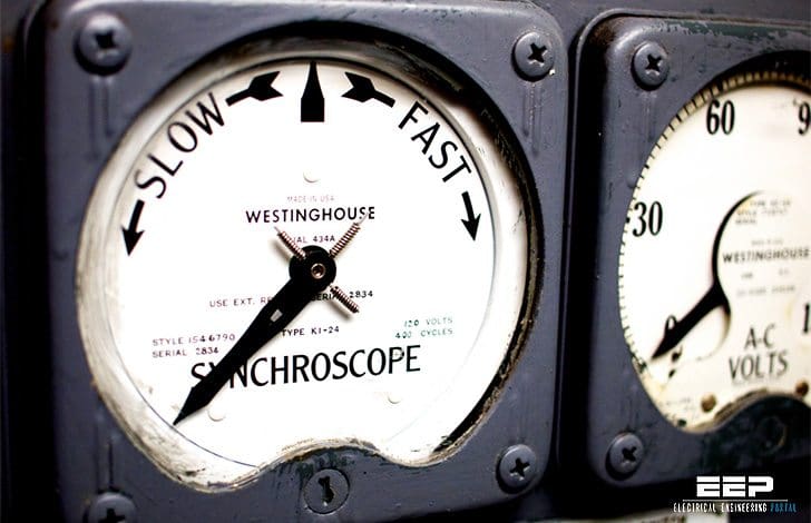 Generator sync check protective function - ANSI 25 (on photo: Vintage generator synchroscope; credit: Jack Amick via Flickr)
The 1.5 per-unit value was measured by a shaft torsional monitoring data acquisition system (EPRI project) at a large coal plant that was paralleled to the 500 kV bulk power electrical system with a 12-degree angular difference during synchronization. Plant operations acknowledged that the turbine deck really shook.
Although turbines are generally built to with- stand angular differences above 10 degrees, most manufacturers recommend limiting out-of-phase synchronizing operations to no more than 10 degrees maximum.
Generator sync-check relays should supervise both manual and automatic modes of operation to prevent generator damage from operator errors or from malfunctioning automatic synchronizing relays.
A clockwise rotation of the synchroscope in the majority of designs indicates that the generator has a higher speed or frequency than the electrical system. This condition is desirable to reduce the possibility that the unit will be in a motoring mode of operation and trip on reverse power protection when the breaker is closed.
The voltages should be matched during synchronizing with a slightly higher generator voltage to ensure var ow into the system instead of the generator.

Figure 1 provides suggested settings for generator sync-check relays. The proposed default angles are 5 degrees advance and 5 degrees late. The calculations consider circuit breaker closing times and maximum allowable slip rates and determine the minimum seconds per scope revolution and the worst-case angle. The minimum seconds per scope revolutions is provided as a guide for operations or for setting auto synchronizing relays. The scope revolutions cannot go faster and be within the operating range of the sync-check relay.
In this case, the worst-case angle of 8.6 degrees complies with manufacturer’s recommendations not to parallel if the angle exceeds 10 degrees. Experience has shown that the proposed settings are practical and within the operating capability of most turbine-governor control systems.
Other available settings in the newer digital relays might include ratio correction factors for step up transformer taps because generator potentials are normally compared to switchyard high voltage potentials and allowable percent voltage mismatches.
However, plant operators should limit voltage mismatches to less than 5% despite they do not represent real power and the shaft torques are minimal.
Slow breaker protection
Some of the newer digital sync-check relay functions also include slow breaker protection. Once the breaker control signal is dispatched, it seals in, and there is no way to abort the close operation because there is a 52a contact in series with the trip coil that prevents the coil from being energized until the breaker is actually closed.
The slow breaker function could be set to operate breaker failure relaying to clear the adjacent breakers if the angular differences reach 10 degrees or more, indicating that the breaker is slow to close for mechanical reasons.
Maximum amount of symmetrical AC current
The max. amount of symmetrical AC current that flows during synchronizing at rated frequency can be approximated by the expression in Figure 2 below.
Generator side voltage and ohms from Figures 1 and 2 (from previous article) were used in the calculation and reflected to the 765 kV side. The system three-phase 765 kV short circuit ohms were transferred from Figure 3.
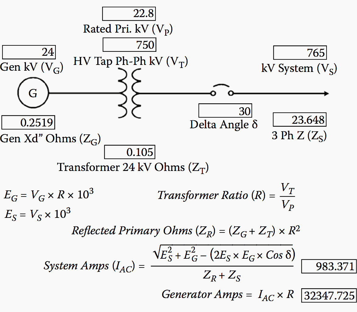
Figure 2 shows that the 765 kV current would be approximately 983 amps and the generator amps would be approximately 32,348 at 30 degrees. At 60, 90, and 180 degrees, the approximated 765 kV currents for the parameters presented in the figure would be 1897, 2682, and 3793 amps, respectively. The generator side current at 180 degrees out would be around 124,767 amps.
This does not include the DC component or peak asymmetrical current, which will also be present.
The air gap torque is difficult to calculate and depends on electromechanical forces, circuit resistance, and the amount of power transfer from angular differences.
Possible damage assessment is particularly complicated and associated with the peak torques and the natural frequencies of the shaft and other mechanical components as the event decays. The associated apparatus may have reduced life from other events or excursions, startup/shutdown cycles, or design or repair oversights, and major equipment damage may occur if the incident is severe enough.
Ηow to synchronize DG1 and DG2 simulator
Reference // Electrical calculations for generating stations by Thomas E. Baker (Purchase hardcopy from Amazon)
Related electrical guides & articles


Edvard Csanyi
Hi, I'm an electrical engineer, programmer and founder of EEP - Electrical Engineering Portal. I worked twelve years at Schneider Electric in the position of technical support for low- and medium-voltage projects and the design of busbar trunking systems.I'm highly specialized in the design of LV/MV switchgear and low-voltage, high-power busbar trunking (<6300A) in substations, commercial buildings and industry facilities. I'm also a professional in AutoCAD programming.
Profile: Edvard Csanyi

what i found here is really use full ,thanks for all usefull information.
i need you that you write to me something,about about how to design for group of disel generating sets to work to gether in synchronism without problems,whether these gen sts are similar to each other or they arent similar to each, and if they are not similar what can be done for operation without problems……thanks
please can i contact you.
this is my mail
[email protected]
Hello sir,
Please tell what are the parameters an auto sync relay would check while sharing load in between two DGs of different rating for their proper synchronization.
Video Unavailable
This video is no longer available because the YouTube account associated with this video has been terminated.
This’s the best website for trainning on electrical enginering
why 1K resistance used in series for 25 relay aux supply
Hi everybody
I am so interested in my major work in teaching electric power to my students
So I would be very grateful to you if i can get more from your website
Best regards
Ahmed M. H. AL-Yousif
I really all postings and thanks for sharing your knowledge. The more you share the more you earn.
Thanks for making me a better Engineer… I am a better person today because of your articles.Thank You