Protective control and monitoring
The purpose of a capacitor bank’s protective control is to remove the bank from service before any units or any of the elements that make up a capacitor unit are exposed to more than 110% of their voltage rating.
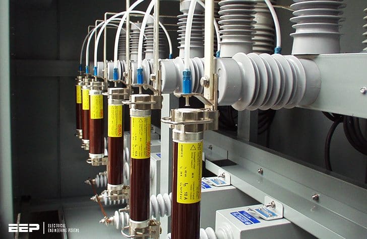
When capacitor units in a capacitor bank fail, the amount of increase in voltage across the remaining units depends on the connection of the bank, the number of series groups of capacitors per phase, the number of units in each series group, and the number of units removed from one series group. A similar effect occurs on the internal elements that make up a capacitor unit.
Such monitoring is desirable for both externally and internally fused units to prevent a cascade failure of the remaining units and their associated fuses.
For the fuseless designs, such a cascade failure would tend to become a short circuit and require the main circuit protection to operate, so it is somewhat more important to detect the failure before it cascades in fuseless banks.
Comparison of operating characteristics of capacitor controls
1. Manual control
| Advantages | Disadvantages |
| No control device necessary, since the bank’s switching device is operated by substation personnel. | Requires attendants at the substation. |
2. Time control
| Advantages | Disadvantages |
| Nonelectrical control input allows application at any point on the circuit. |
|
3. Temperature control
| Advantages | Disadvantages |
| Can only be applied where direct correlation with load increases and temperature can be established, such as air conditioning loads. |
4. Voltage control
| Advantages | Disadvantages |
| Applies and removes shunt capacitors when system voltages operate outside of the allowable voltage tolerances. |
|
5. Current control
| Advantages | Disadvantages |
| Requires current transformer. Adjustment slightly more complex than other controls. |
6. kVAR control
| Advantages | Disadvantages |
|
|
Protective monitoring controls are available for capacitor banks connected Wye-Wye, grounded-neutral capacitor banks, and ungrounded-neutral capacitor banks, as shown in figures 1 and 2.
This topic is discussed further below in Protection of capacitor Banks.
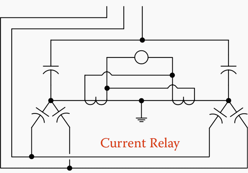

The above scheme applicable to double Wye-configured banks is shown in figure 1. This scheme detects the current that ows when an unbalance exists between the neutrals of two ungrounded banks.
For Delta banks, a similar principle can be adopted using an “H” configuration of capacitors on each phase.
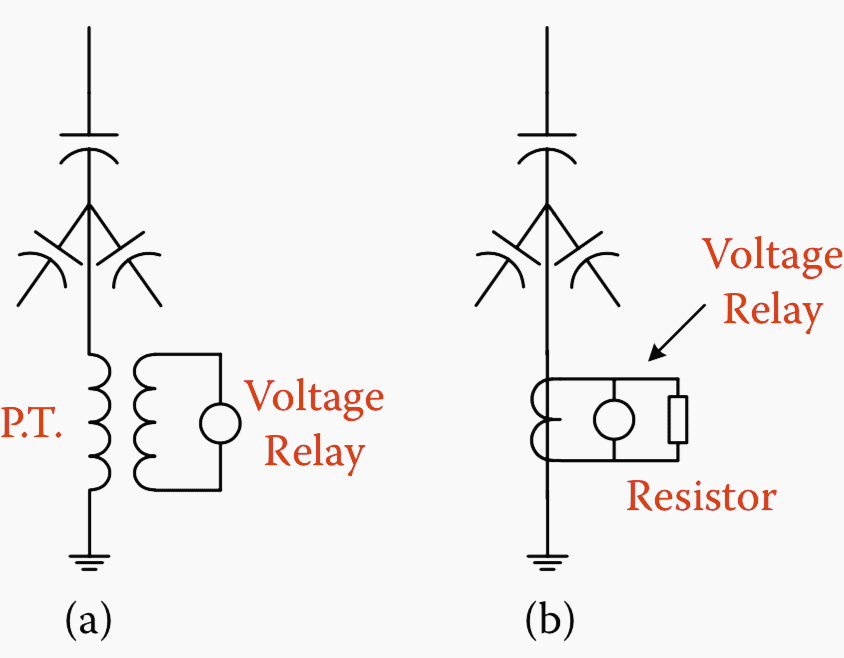

For single Wye-grounded neutral capacitor banks, the most straight-forward protective control is neutral-current-type relaying. This scheme operates on the neutral current generated because of the unbalance caused by capacitor failures in any phase.
If there are not too many series sections, this monitoring control can be set to alarm and trip at two different levels of neutral current to provide (a) early detection that a problem exists in the bank and (b) adequate protection should additional capacitor units fail.
The floating-neutral protective control is similar to that for an ungrounded neutral bank, except that a voltage transformer (VT) is used in the neutral (usually rated 15 kV) to indicate neutral voltage shift upon loss of units.
The control voltage is sensitive and subject to the same limitations and advantages as the protective control for grounded-neutral capacitor banks.
How to select capacitor protection?
The capacitor protection consists of:
- Fuses for individual capacitor unit protection
- Circuit breakers with fault- and condition-monitoring relaying or circuit breaker for capacitor-bank protection
Fuse for individual capacitor unit protection
The following criteria are applied for the selection of capacitor fuses for individual units and for externally fused capacitors used in capacitor banks.
The internal fuses for internally fused units used in capacitor banks follow the same basic criteria, but in those cases, the fuse characteristics are applied by the manufacturer:
Voltage rating – Must be larger than the capacitor unit voltage rating.
Continuous current rating – The fuse must carry at least 165% of capacitor current for grounded banks and 150% for ungrounded banks. This includes allowance for harmonics, capacitor unit tolerance, and overvoltage.
Short circuit (interrupting) – Must be greater than the short-circuit current that will ow when the capacitor unit is shorted.
Time–current characteristics- The fuse must clear the overcurrent due to a failed unit, preferably in 30 s or less or 300 s maximum.
- The time–current curve must lie below or to the left of the case (can) rupture curve.
Relaying for capacitor-bank protection
Relaying for capacitor-bank protection includes overcurrent (for fault protection), overvoltage, system problem detection, and current or voltage unbalance, depending on bank configuration, for monitoring the condition of the capacitor units.
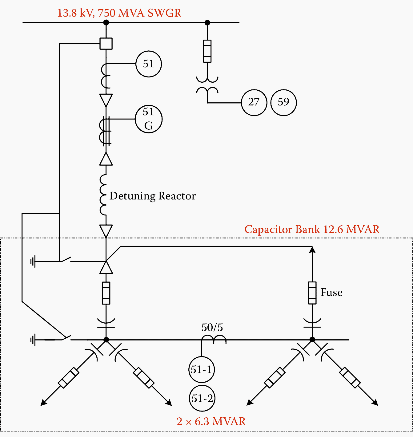
The protection scheme for a typical 12.6 MVAR (2 × 6.3 MVAR connected in double Wye) capacitor bank with external fuses and a series detuning reactor is show in Figure 3.

Overcurrent relay for capacitor-bank protection
A time-overcurrent relay, device 51, with an inverse or very inverse characteristic, is used for capacitor-bank fault protection. The current pickup is set at about 150–200% of the bank current rating, and the time dial is adjusted to override the maximum inrush current upon energizing or switching.
Undervoltage and overvoltage protection
The bus-connected overvoltage relay is a time-delayed relay and is set to trip the bank if the system voltage exceeds the total voltage rating of the bank and before the unit voltage withstand time is exceeded.
The undervoltage is provided to trip the bank for the loss of system voltage and is time-delayed to allow for parallel fault clearance and other transient voltage excursions.
Current-unbalance / voltage-unbalance protection
Current-unbalance or voltage-unbalance relays are used to detect the loss of capacitor units within a bank and protect the remaining units against overvoltage. The relays must be set above the inherent unbalance that is caused by the capacitor tolerance, system voltage unbalance, and harmonic current or voltage.
The schemes to detect voltage or current unbalance between the neutrals of two ungrounded banks are shown in Figure 4a and 4b, respectively. Both schemes are insensitive to system voltage unbalance and third-harmonic current or voltage.
This scheme is applicable to double Wye-configured banks.
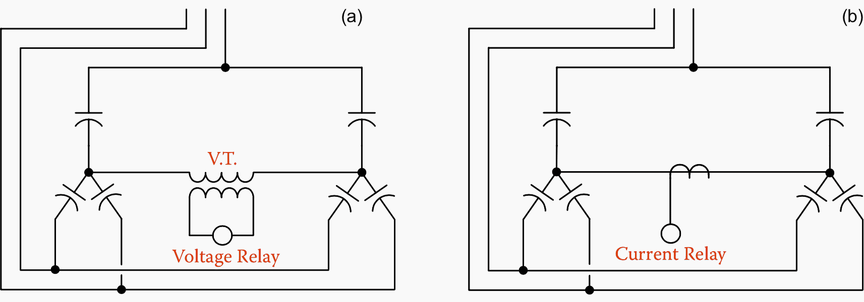

A similar scheme can be applied on a phase-by-phase basis when multiples of four capacitor units are connected in “H” con guration with the CT (or VT) connected in the connection between the midpoints of the two pairs of capacitors that make up the “H.”
This variant can be used for a single Wye- or for Delta-connected banks.
SEL-487V capacitor protection relay test procedure
Reference // Industrial power systems by Khan, Shoaib (Purchase hardcover from Amazon)




Need your advice. We have lots of capacitor banks at the moment which are having burned/overheated cables and contactors. May i know what could have caused this phenomenon? Almost all of them installed in different locations. Could it be design issue? Need you guys help, thanks! 🙏🏼
We have lots of capacitor banks at the moment which are having burned/overheated cables and contactors. May i know what could have caused this phenomenon? Almost all of them installed in different locations. Could it be design issue? Need you guys help, thanks! 🙏🏼
Hello
We also have a lot of capacitor bank.
If you get the answer of your question, please contact me.
Thank you in advance.
The guide is very useful.
I learning to install a new capacitor capacitor banks in my network during renovation. nonetheless i still waiting for PDF to learn more.
You offered good information on relaying for capacitor bank protection. We are having a problem choosing a breaker (or one-shot recloser) for protecting a 13.8 kV substation bus from a fault in a 3 MVA STATCOM in the substation. Also for a 5 kVAR filter tuned to 4.8 th harmonic. Opening a faulted phase and re-striking on an un-faulted phase is our main concern. Thank you.
Should have said 5 MVAR not 5 kVAR in previous comment. Thanks.
this guide is very useful, it just comes at the right moment as we have a project to upgrade our banks and some of what is mentioned in this article will sure guide us to select the better protection available to preserve lifespan.